Story
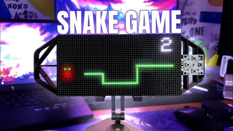
Welcome back, everyone! In this fun DIY project, we’ll be building a Snake Game Console—a portable, retro-style gaming device powered by the Raspberry Pi Pico 2. The console features a custom-designed Raspberry Pi Pico 2 driver circuit and a 64×32 RGB P3 Matrix Panel, bringing a compact, handheld gaming experience to life.
In this project, we designed and built a portable Snake Game Console using Fusion 360 for 3D modeling, a Raspberry Pi Pico 2 for the hardware, and a 64×32 RGB Matrix Panel for the display. We also used custom PCBs to integrate the electronics and bring the console to life.
Design and Assembly
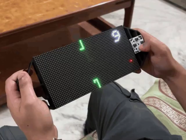
We began by modeling the console’s frame in Fusion 360, then 3D printed the parts and assembled them with the RGB Matrix Panel and custom PCBs. The result is a handheld game console that allows you to play the classic Snake Game on a custom-built device.
For the game itself, we developed the traditional Snake game from scratch. The game includes:
A Snake entity controlled by four directional buttons
A randomly appearing Red Dot on the matrix panel, which the snake must “eat”
A Score marker in the top-right corner to track how many red dots the snake consumes
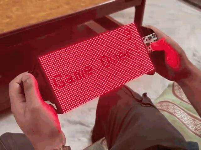
The game ends when the snake bites its own body, adding a classic challenge to the gameplay.
Powering the Console
The console is powered by a 3.7V 2600mAh lithium-ion battery, providing ample power for portable gaming. This onboard power source allows you to take the game anywhere and enjoy it on the go.
Materials Required
Here’s a list of the materials used in this project:
Hardware Components:
Custom PCBs
Raspberry Pi Pico 2
64×32 RGB Matrix Panel
IP5306 IC
10uF Capacitors
USB Micro Port
18650 Lithium Cell
18650 Cell Holder (SMD version)
Push Buttons
Fabrication:
3D Printed Parts
64×32 RGB Matrix Panel: An Overview
In this project, we are using the 64×32 RGB Matrix Panel to bring our Snake Game Console to life. This panel is made up of 2048 RGB LEDs arranged in a 64×32 grid, capable of displaying vibrant text, graphics, and animations with excellent clarity and color.
How the 64×32 RGB Matrix Panel Works
The HUB75 interface is used to control this matrix, which includes several important pins:
RGB pins for color data
Address pins (A, B, C, D)
Clock (CLK) and Latch (LAT) signals
Data Latch
Output Enable (OE) pin
The matrix operates using the row-column scanning technique. This method shifts a row of pixel data into a shift register, which then uses a demultiplexer to select which rows are displayed. This allows the matrix to efficiently display complex visuals while keeping the data load manageable.
Connecting Multiple Panels
You can link multiple RGB matrix panels in a chain to extend the display area. The panels can be connected using the provided IN and OUT pins. However, when linking multiple panels, it’s important to ensure that the control unit (in this case, the Raspberry Pi Pico 2) can handle the increased data load. This is one of the key challenges when scaling up the display.
The Waveshare RGB-Matrix-P3 is the model used in this project, and you can find more detailed specifications and setup guides on the official Waveshare wiki.
Console Design: 3D Modeling and Assembly
The first step in building the Snake Game Console was designing the 3D model of the console. The design incorporates two handgrip-like components attached to the back side of the 64×32 RGB Matrix Panel for comfortable handheld gameplay. Additionally, we created a model for the special button board, which is mounted on one side of the console.
Component Placement and Assembly
The PICO Driver Circuit is fastened to the Handgrip frame using four spacers and is positioned at the back of the device. This ensures the circuit is securely held while maintaining a compact form factor for portability.
To mount the handgrip frame to the matrix panel, we utilized the three M3 inserts already present on the RGB matrix. The handgrip frame components are then attached from the back of the matrix panel, ensuring stability and ease of access.
Each handgrip has three mounting holes, allowing us to use M3 bolts to secure the handgrips to the matrix panel. This ensures a firm and reliable attachment, making the device sturdy and comfortable to hold during gameplay.
On the side of the console, the button board is secured using four M2 screws. These buttons control the Snake game, making them a critical part of the user interface.
3D Printing the Console Parts
Once the 3D model was complete, we exported the mesh files for the left and right handgrips, along with the four spacers. We used a 0.6mm nozzle to 3D print the parts in black PLA, which provided a strong and durable finish.
PCB Design: PICO Driver
In this phase of the project, we designed the PICO Driver Board using PCB CAD software to create the necessary schematic. This board connects the Raspberry Pi Pico 2 to the 64×32 RGB Matrix Panel via the HUB75 connector.
Wiring the HUB75 Connector to the PICO 2
To establish the connection between the PICO 2 and the RGB Matrix, we used a CON 16 connector. We connected the matrix’s HUB75 pins (CON 16) to the GPIO pins on the Raspberry Pi Pico 2 as follows:
A → GPIO19
B → GPIO16
C → GPIO18
D → GPIO20
E → GPIO22
CLK → GPIO11
LAT/STB → GPIO12
OE → GPIO13
R1 → GPIO2
G1 → GPIO3
B1 → GPIO4
R2 → GPIO5
G2 → GPIO8
B2 → GPIO9
This ensures the proper communication between the Raspberry Pi Pico 2 and the RGB Matrix Panel for rendering the game display.
Button Connections and User Input
We also added a CON5 connector for user inputs. This connector has four pins that are connected to the Pico’s GPIO pins (GPIO6, GPIO7, GPIO14, GPIO15) for the directional buttons. The GND pin on CON5 is connected to the fifth pin of the connector, enabling the buttons to pull the GPIOs to ground when pressed. This allows the Pico to detect button presses and control the game accordingly.
Power Management: IP5306 Power IC
To manage power, we incorporated the IP5306 power management IC. This integrated multi-function power management SoC is essential for powering the Pico 2 and the RGB Matrix. It provides a steady 5V at 2.1A using a 3.7V lithium-ion battery as input, which is sufficient to power both the display and the Raspberry Pi.
For more detailed specifications of the IP5306, you can check out the IP5306 Datasheet.
Board Layout and Final Design
Once the schematic was complete, we exported the netlist and began creating the PCB board layout. The Pico 2, button connections, lithium cell holder, and USB mini port were placed on the top side of the board, while all SMD components were placed on the bottom side to ensure an efficient and organized design.
PCB Design: Button Board
Next, we get the Schematic for Button Board prepared. It has four push buttons, with the 4 and 3 pins of each button connected to GND. Additionally, there is a CON5 connector that is attached to each connector’s 1 and 2 for GPIO and 3 and 4 for GND.
After setting up the schematic, we used the PCB editor to prepare the board file by aligning the buttons in the proper location and following exactly to the CAD file layout
PCB Assembly: PICO Driver Board Construction
The assembly of the PICO Driver Board begins with applying solder paste to the SMD component pads using a solder paste dispensing needle. In this case, we use a 63/37 Sn/Pb solder paste for reliable and efficient soldering.
Placing SMD Components on the PCB
After applying the solder paste, we use ESD tweezers to carefully position each SMD component on the PCB. Proper placement is crucial to ensure reliable electrical connections.
Reflow Soldering Process
Once the components are positioned, we place the PCB on a reflow hotplate. The hotplate gradually raises the temperature of the PCB, melting the solder paste and securely attaching all SMD components. The temperature reaches 190°C, which is the melting point of the solder paste, allowing for a strong and reliable bond between the components and the PCB.
Finalizing Component Assembly
After the reflow process, we flip the board over to solder the 18650 holder in place using a soldering iron. Next, we install the USB Micro port and push switch, ensuring the components are securely soldered on both sides of the PCB.
Testing the Power Section
Before continuing with the final assembly, we stop and verify the power module circuits. We insert a 3.7V 2600mAh lithium-ion battery into the 18650 holder, ensuring the correct polarity. Once the battery is in place, we press the push button to power on the device.
We use a multimeter to check the output voltage, which should be a steady 5V. If the power section is functioning correctly, we proceed to attach the Raspberry Pi Pico 2 to the PCB and continue with the remaining assembly steps.
PCB ASSEMBLY: PICO DRIVER (Rest of the Assembly)
PICO Driver Board Assembly
To finalize the PICO Driver Board, we begin by positioning two female CON 20 header pins on the Raspberry Pi Pico 2 footprint and two male CON 8 header pins on the HUB75 connector footprint. After aligning these components, we flip the PCB over and use a soldering iron to securely solder the header pin pads into place.
Once the headers are soldered, we reinstall the lithium cell into its holder and position the Raspberry Pi Pico 2 over the CON 20 header pins to complete the PICO Driver assembly.
Button Board Assembly
Next, we begin the assembly of the Button Board. The process starts with positioning the push buttons on the top side of the board. After they are aligned, we flip the board over and solder the button pads from the bottom side, ensuring secure and reliable button connections.
PICO Driver and Matrix Assembly
Connecting the PICO Driver to the Matrix
With the Wire Harness provided in the Matrix Kit, we connect the PICO Driver and the 64×32 RGB Matrix. We start by soldering the positive wire of the harness to the 5V output on the PICO Driver and the negative wire to the GND pin.
Next, we attach the female connector of the Wire Harness to the male connector on the matrix. This ensures a stable connection between the two components.
Connecting the HUB75 Wire Harness
We then use the HUB75 Wire Harness to connect the matrix and PICO Driver GPIOs. The harness is plugged into the matrix’s connector first, followed by connecting the other end to the PICO Driver. This completes the essential wiring for communication between the two devices.
Testing the Configuration: Game of Life
Once the hardware assembly is complete, we proceed to test the configuration. We first connect the Matrix and PICO Driver. Then, we flash the PICO 2 with our converted Game of Life code, which we derived from an example sketch in the FastLED library. Running this sketch allows us to verify if the hardware setup is correctly configured and functioning as expected.
TEST SKETCH: GAME OF LIFE
We connected the Mattrix and PICO DRIVE first, then flashed the PICO using our previously converted Game of Life code that we had taken from an example sketch of the FastLED library to see if our configuration worked.
The remarkable cellular automaton known as the “Game of Life” was developed in 1970 by British mathematician John Horton Conway. Since it is a zero-player game, no extra input is required; rather, the game’s progression is determined by its initial state.
Checkout more about game of life from here-
The game will start with a random configuration and restart with a new random configuration after it halts and yes this setup is Turing complete.
#include <Adafruit_Protomatter.h>// Pin definitions
#define R1 2
#define G1 3
#define B1 4
#define R2 5
#define G2 8
#define B2 9
#define A 10
#define B 16
#define C 18
#define D 20
#define CLK 11
#define LAT 12
#define OE 13
#define WIDTH 64
#define HEIGHT 32
uint8_t rgbPins[] = { R1, G1, B1, R2, G2, B2 };
uint8_t addrPins[] = { A, B, C, D };
Adafruit_Protomatter matrix(WIDTH, HEIGHT, 1, rgbPins, 4, addrPins, CLK, LAT, OE, false);
bool grid[WIDTH][HEIGHT];
bool newGrid[WIDTH][HEIGHT];
void setup() {
matrix.begin();
randomSeed(analogRead(0));
// Initialize grid with random values
for(int x = 0; x < WIDTH; x++) {
for(int y = 0; y < HEIGHT; y++) {
grid[x][y] = random(2);
}
}
}
void loop() {
matrix.fillScreen(0);
// Update grid based on Game of Life rules
for(int x = 0; x < WIDTH; x++) {
for(int y = 0; y < HEIGHT; y++) {
int aliveNeighbors = countAliveNeighbors(x, y);
if(grid[x][y]) {
// Any live cell with two or three live neighbors survives.
if(aliveNeighbors < 2 || aliveNeighbors > 3) {
newGrid[x][y] = false;
} else {
newGrid[x][y] = true;
}
} else {
// Any dead cell with three live neighbors becomes a live cell.
if(aliveNeighbors == 3) {
newGrid[x][y] = true;
} else {
newGrid[x][y] = false;
}
}
if(newGrid[x][y]) {
matrix.drawPixel(x, y, matrix.color565(255, 255, 255)); // White color
}
}
}
// Copy newGrid to grid
memcpy(grid, newGrid, sizeof(grid));
matrix.show();
delay(100); // Adjust the delay for speed control
// Check if the grid is stable or empty
if(isGridStableOrEmpty()) {
resetGrid();
}
}
int countAliveNeighbors(int x, int y) {
int aliveNeighbors = 0;
for(int dx = –1; dx <= 1; dx++) {
for(int dy = –1; dy <= 1; dy++) {
if(dx == 0 && dy == 0) continue;
int nx = (x + dx + WIDTH) % WIDTH;
int ny = (y + dy + HEIGHT) % HEIGHT;
if(grid[nx][ny]) {
aliveNeighbors++;
}
}
}
return aliveNeighbors;
}
bool isGridStableOrEmpty() {
for(int x = 0; x < WIDTH; x++) {
for(int y = 0; y < HEIGHT; y++) {
if(grid[x][y]) {
return false;
}
}
}
return true;
}
void resetGrid() {
for(int x = 0; x < WIDTH; x++) {
for(int y = 0; y < HEIGHT; y++) {
grid[x][y] = random(2);
}
}
}
Weare using theAdafruit_Protomatterlibrary here which you need to install on your Arduino IDE before using this code.
FRAME & MATRIX ASSEMBLY
Attaching the 3D-Printed Handgrips to the RGB Matrix
The assembly of the Snake Game Console begins with aligning the mounting holes of the two 3D-printed handgrip frames with the corresponding holes on the RGB Matrix Panel. Once aligned, we use six M3 bolts to secure the handgrip frames to the back of the matrix. Thanks to the M3 Brass Inserts added to the back of the matrix, we can easily tighten the bolts and ensure a stable connection between the handgrip frames and the matrix.
Button Board Frame Assembly
Next, we position the button board from the front of the console. Using four M2 screws, we secure the button board in place, ensuring it is properly aligned and fixed to the console’s frame for durability and ease of use during gameplay.
PICO Driver & Frame Assembly
For the PICO Driver assembly, we use four 3D-printed spacers to position the PICO Driver on the back side of the console. The spacers are placed over the mounting holes on the frame to create a secure and elevated position for the PICO Driver. We then use M3 screws to fasten the PICO Driver to the frame, ensuring it remains firmly attached and properly aligned for optimal performance.
Final Wiring Connections: Button Board & PICO Driver
The last step in the assembly process involves wiring the DPAD Button PCB to the PICO Driver Board. We begin by adding five connecting wires to the CON5 port on the button board. Then, we connect each wire to the corresponding GPIO pins on the PICO Driver in the following pin order:
UP pin → GPIO7
DOWN pin → GPIO6
LEFT pin → GPIO15
RIGHT pin → GPIO14
After connecting the wires, we carefully tuck away the excess wire length within the console frame and secure the wires using a small amount of hot glue to ensure they stay in place and do not interfere with other components.
With the wiring complete, the Snake Game Console assembly is now finished and ready for testing.
Main Code
Here’s the main code used in this project. It’s a simple and efficient implementation to control the Snake game on the 64×32 RGB matrix.
#include <Adafruit_Protomatter.h>
// Pin definitions
#define R1 2
#define G1 3
#define B1 4
#define R2 5
#define G2 8
#define B2 9
#define A 10
#define B 16
#define C 18
#define D 20
#define CLK 11
#define LAT 12
#define OE 13
// Button pins
#define BUTTON_UP 7
#define BUTTON_DOWN 6
#define BUTTON_LEFT 15
#define BUTTON_RIGHT 14
#define WIDTH 64
#define HEIGHT 32
#define SNAKE_LENGTH 8
uint8_t rgbPins[] = { R1, G1, B1, R2, G2, B2 };
uint8_t addrPins[] = { A, B, C, D };
Adafruit_Protomatter matrix(WIDTH, HEIGHT, 1, rgbPins, 4, addrPins, CLK, LAT, OE, false);
struct SnakeSegment {
int x;
int y;
};
SnakeSegment snake[WIDTH * HEIGHT]; // Increased size to allow snake growth
int snakeLength = SNAKE_LENGTH;
int dx = 1, dy = 0;
uint16_t snakeColor = matrix.color565(0, 255, 0); // Green color
uint16_t foodColor = matrix.color565(255, 0, 0); // Red color
uint16_t gameOverColor = matrix.color565(255, 0, 0); // Red color for "Game Over" screen
int foodX, foodY;
int score = 0; // Score variable
bool gameOver = false; // Game over flag
void placeFood() {
// Ensure the new food position does not overlap with the snake
bool foodOnSnake;
do {
foodX = random(WIDTH);
foodY = random(HEIGHT);
foodOnSnake = false;
for (int i = 0; i < snakeLength; i++) {
if (snake[i].x == foodX && snake[i].y == foodY) {
foodOnSnake = true;
break;
}
}
} while (foodOnSnake);
}
void setup() {
matrix.begin();
pinMode(BUTTON_UP, INPUT_PULLUP);
pinMode(BUTTON_DOWN, INPUT_PULLUP);
pinMode(BUTTON_LEFT, INPUT_PULLUP);
pinMode(BUTTON_RIGHT, INPUT_PULLUP);
// Initialize snake in the middle of the screen
for (int i = 0; i < snakeLength; i++) {
snake[i] = { WIDTH / 2 - i, HEIGHT / 2 };
}
placeFood(); // Place initial food
// Clear screen
matrix.fillScreen(matrix.color565(0, 0, 0));
matrix.show();
}
void drawScore() {
matrix.setCursor(WIDTH - 10, 2); // Adjust cursor to top-right corner
matrix.setTextColor(matrix.color565(255, 255, 255)); // Set text color to white for visibility
matrix.print(score); // Display only the score number
}
void checkGameOver() {
// Check if snake collides with itself
for (int i = 1; i < snakeLength; i++) {
if (snake[0].x == snake[i].x && snake[0].y == snake[i].y) {
gameOver = true;
break;
}
}
}
void resetGame() {
snakeLength = SNAKE_LENGTH;
dx = 1;
dy = 0;
score = 0;
gameOver = false;
// Initialize snake in the middle of the screen
for (int i = 0; i < snakeLength; i++) {
snake[i] = { WIDTH / 2 - i, HEIGHT / 2 };
}
placeFood(); // Place initial food
}
void drawGameOver() {
// Fill the screen with red
matrix.fillScreen(gameOverColor);
// Draw "Game Over!" in black
uint16_t blackColor = matrix.color565(0, 0, 0);
matrix.setCursor((WIDTH / 2) - 30, (HEIGHT / 2) - 4);
matrix.setTextColor(blackColor);
matrix.print("Game Over!");
// Display score in white
matrix.setCursor(WIDTH - 10, 2); // Adjust cursor to top-right corner
matrix.setTextColor(blackColor);
matrix.print(score);
}
void loop() {
if (gameOver) {
drawGameOver();
matrix.show();
delay(5000); // Wait 5 seconds
resetGame(); // Reset the game
return;
}
// Check button states and update direction
if (!digitalRead(BUTTON_UP) && dy == 0) {
dx = 0; dy = -1;
} else if (!digitalRead(BUTTON_DOWN) && dy == 0) {
dx = 0; dy = 1;
} else if (!digitalRead(BUTTON_LEFT) && dx == 0) {
dx = -1; dy = 0;
} else if (!digitalRead(BUTTON_RIGHT) && dx == 0) {
dx = 1; dy = 0;
}
// Move snake
for (int i = snakeLength - 1; i > 0; i--) {
snake[i] = snake[i - 1];
}
snake[0].x += dx;
snake[0].y += dy;
// Wrap around screen edges
if (snake[0].x >= WIDTH) snake[0].x = 0;
if (snake[0].x < 0) snake[0].x = WIDTH - 1;
if (snake[0].y >= HEIGHT) snake[0].y = 0;
if (snake[0].y < 0) snake[0].y = HEIGHT - 1;
// Check if snake eats the food
if (snake[0].x == foodX && snake[0].y == foodY) {
snakeLength++;
score++; // Increment score
placeFood();
}
// Clear screen
matrix.fillScreen(matrix.color565(0, 0, 0));
// Draw snake
for (int i = 0; i < snakeLength; i++) {
matrix.drawPixel(snake[i].x, snake[i].y, snakeColor);
}
// Draw food
matrix.drawPixel(foodX, foodY, foodColor);
// Draw score
drawScore();
// Update display
matrix.show();
// Check for game over
checkGameOver();
delay(100); // Adjust delay for speed control
}
This code is divided into seven sections which are the following-
Library and Pin Definitions- which includes the Adafruit_Protomatter Library to control the RGB Matrix along with the Pins for RGB Signal, Address lines, clock, Snake length, latch and outoput enable as well as buttons are also defined here.
#include <Adafruit_Protomatter.h>
// Pin definitions
#define R1 2
#define G1 3
#define B1 4
#define R2 5
#define G2 8
#define B2 9
#define A 10
#define B 16
#define C 18
#define D 20
#define CLK 11
#define LAT 12
#define OE 13
// Button pins
#define BUTTON_UP 7
#define BUTTON_DOWN 6
#define BUTTON_LEFT 15
#define BUTTON_RIGHT 14
#define WIDTH 64
#define HEIGHT 32
#define SNAKE_LENGTH 8
Matrix Initialization and Snake Structure- Here, the matrix is set up with width, height, RGB pins, address pins, clock, latch, and output enable. the snake structure Defines the structure for the snake’s segments, initializing snake length, direction, colors, food position, score, and game over flag.
uint8_t rgbPins[] = { R1, G1, B1, R2, G2, B2 };
uint8_t addrPins[] = { A, B, C, D };
Adafruit_Protomatter matrix(WIDTH, HEIGHT, 1, rgbPins, 4, addrPins, CLK, LAT, OE, false);
struct SnakeSegment {
int x;
int y;
};
SnakeSegment snake[WIDTH * HEIGHT]; // Increased size to allow snake growth
int snakeLength = SNAKE_LENGTH;
int dx = 1, dy = 0;
uint16_t snakeColor = matrix.color565(0, 255, 0); // Green color
uint16_t foodColor = matrix.color565(255, 0, 0); // Red color
uint16_t gameOverColor = matrix.color565(255, 0, 0); // Red color for “Game Over” screen
int foodX, foodY;
int score = 0; // Score variable
bool gameOver = false; // Game over flag
Place Food Function- Places food on the matrix, ensuring it doesn’t overlap with the snake’s position.
void placeFood() {
  bool foodOnSnake;
  do {
    foodX = random(WIDTH);
    foodY = random(HEIGHT);
    foodOnSnake = false;
    for (int i = 0; i < snakeLength; i++) {
      if (snake[i].x == foodX && snake[i].y == foodY) {
        foodOnSnake = true;
        break;
      }
    }
  } while (foodOnSnake);
}
Setup Function- Initializes the matrix and button pins. Positions the snake in the middle of the screen and places the initial food.
void setup() { matrix.begin();
pinMode(BUTTON_UP, INPUT_PULLUP);
pinMode(BUTTON_DOWN, INPUT_PULLUP);
pinMode(BUTTON_LEFT, INPUT_PULLUP);
pinMode(BUTTON_RIGHT, INPUT_PULLUP);// Initialize snake in the middle of the screen
for (int i = 0; i < snakeLength; i++) {
snake[i] = { WIDTH / 2 – i, HEIGHT / 2 };
}
placeFood(); // Place initial food
// Clear screen
matrix.fillScreen(matrix.color565(0, 0, 0));
matrix.show();
}
Drawing Functions-drawScore displays the score on the screen. drawGameOver displays the “Game Over” message and the score.
void drawScore() {
  matrix.setCursor(WIDTH - 10, 2);
  matrix.setTextColor(matrix.color565(255, 255, 255));
  matrix.print(score);
}
void drawGameOver() {
matrix.fillScreen(gameOverColor);
uint16_t blackColor = matrix.color565(0, 0, 0);
matrix.setCursor((WIDTH / 2) – 30, (HEIGHT / 2) – 4);
matrix.setTextColor(blackColor);
matrix.print(“Game Over!”);
matrix.setCursor(WIDTH – 10, 2);
matrix.setTextColor(blackColor);
matrix.print(score);
}
Game Logic Functions-checkGameOver checks if the snake collides with itself, setting the game over flag. resetGame resets the game variables and initializes the snake position.
void checkGameOver() {
  for (int i = 1; i < snakeLength; i++) {
    if (snake[0].x == snake[i].x && snake[0].y == snake[i].y) {
      gameOver = true;
      break;
    }
  }
}
void resetGame() {
snakeLength = SNAKE_LENGTH;
dx = 1;
dy = 0;
score = 0;
gameOver = false;
for (int i = 0; i < snakeLength; i++) {
snake[i] = { WIDTH / 2 – i, HEIGHT / 2 };
}
placeFood();
}
Main Loop- Controls the main game logic, including snake movement, food placement, score updates, drawing, and game-over checks.
void loop() {
  if (gameOver) {
    drawGameOver();
    matrix.show();
    delay(5000);
    resetGame();
    return;
  }
if (!digitalRead(BUTTON_UP) && dy == 0) {
dx = 0; dy = –1;
} else if (!digitalRead(BUTTON_DOWN) && dy == 0) {
dx = 0; dy = 1;
} else if (!digitalRead(BUTTON_LEFT) && dx == 0) {
dx = –1; dy = 0;
} else if (!digitalRead(BUTTON_RIGHT) && dx == 0) {
dx = 1; dy = 0;
}
for (int i = snakeLength – 1; i > 0; i–) {
snake[i] = snake[i – 1];
}
snake[0].x += dx;
snake[0].y += dy;
if (snake[0].x >= WIDTH) snake[0].x = 0;
if (snake[0].x < 0) snake[0].x = WIDTH – 1;
if (snake[0].y >= HEIGHT) snake[0].y = 0;
if (snake[0].y < 0) snake[0].y = HEIGHT – 1;
if (snake[0].x == foodX && snake[0].y == foodY) {
snakeLength++;
score++;
placeFood();
}
matrix.fillScreen(matrix.color565(0, 0, 0));
for (int i = 0; i < snakeLength; i++) {
matrix.drawPixel(snake[i].x, snake[i].y, snakeColor);
}
matrix.drawPixel(foodX, foodY, foodColor);
drawScore();
matrix.show();
checkGameOver();
delay(100);
}
The loop checks for button inputs to control the direction of the snake, updates the snake’s position, handles screen wrapping, checks for food consumption, and updates the display. If the game is over, it displays the “Game Over” message, waits for 5 seconds, and then resets the game.
RESULT
https://youtu.be/dtTepy-05BE?si=SnouN-jcIgs6VxhN
End Result: Functional Handheld Snake Game Console
After a long yet straightforward build process, the Snake Game Console is now fully functional and ready for use. This portable console is equipped with an integrated battery, allowing users to carry it around and enjoy games on the go.
Gameplay Features
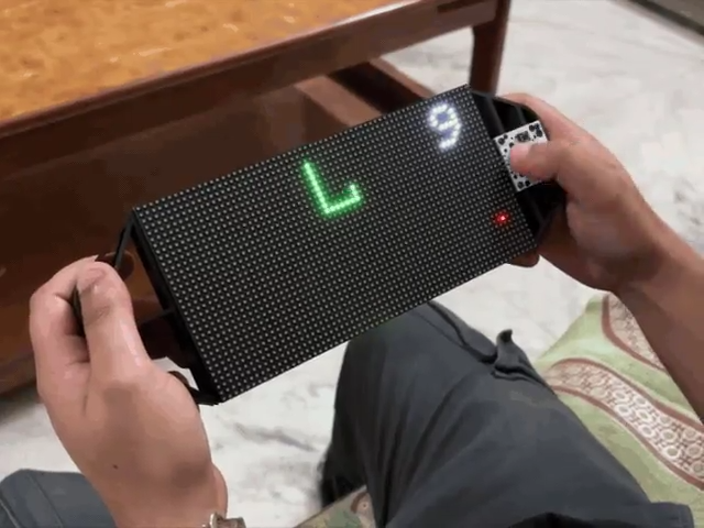
The console is controlled via the DPad, and the objective of the Snake game is to consume as many red dots (food) as possible. The score marker in the upper-right corner of the screen tracks the player’s progress.
One exciting feature is that Snake can cross the display boundaries. However, if the snake accidentally collides with itself, the game ends. A red “Game Over” screen will appear, showing the final score. After a short five-second pause, the game will automatically restart.
To power the device on or off, simply press the PUSH button located on the back of the console.
Charging and Power Management
The console can be charged using a Micro B cable and any standard 5V smartphone charger. During charging, the status LED will blink. Once the battery is fully charged, the LED will stop blinking and remain on.
Successful Project Completion
This Snake Game Console project was a success, and I’m pleased with the result. While there’s no immediate plan for a V2 of this console, the Snake Game Console can be adapted to run virtually any game, though porting existing games or creating new ones will be topics for future projects.
Acknowledgments and Resources
All the necessary documents, files, and code are included in the article for your reference, should you wish to replicate or modify the project. Additionally, a big thank you to PCBWAY for their support. They offer a wide range of PCB-related services, including stencil and PCB assembly services, and 3D printing.
Thanks for following along with this project! I’ll be back with new projects soon.
Peace!
Custom parts and enclosures
SCROLL DOWN TO DOWNLOAD FILES


