Things Used in This Project
Hardware Components
Raspberry Pi 5 × 1
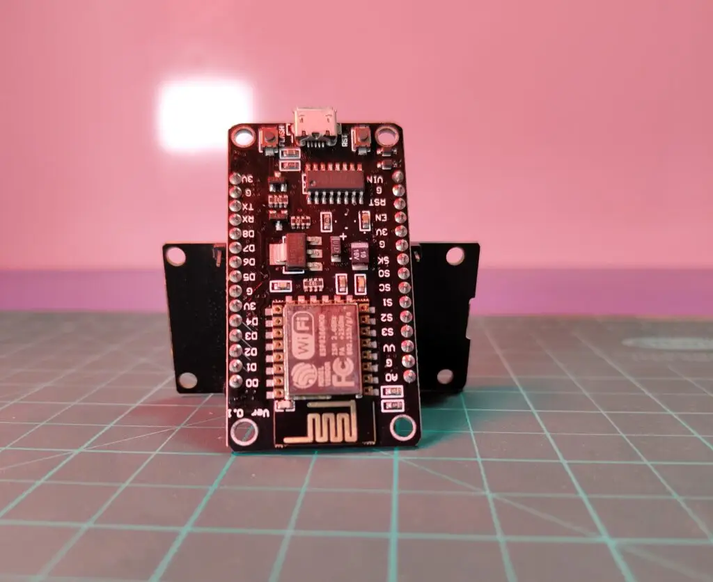
Seeed Studio XIAO SAMD21 (Pre-Soldered) – Seeeduino XIAO × 1
Software & Online Tools
Autodesk Fusion – for 3D modeling and design
Arduino IDE – used for programming the microcontroller
Tools & Fabrication Equipment
Seeed Studio Fusion PCB/PCBA Service – for custom PCB manufacturing and assembly
Story
Hello everyone, and welcome back!
Today, we're diving into something exciting — the Pi1000: a DIY alternative to the Raspberry Pi 400. It's a compact, keyboard-integrated computer powered by the Raspberry Pi 5.
This build uses the new PCIe M.2 Shield alongside an NVMe SSD and the 4GB variant of the Raspberry Pi 5. Much like the official Raspberry Pi 400, our design integrates the entire Pi setup within a keyboard enclosure.
Boot-up is impressively fast — it takes just 5 to 6 seconds to reach the desktop, thanks to the power of the Pi 5 combined with the NVMe SSD.
We're using a Gen 3x4 SSD that supports PCIe Express 3.1, capable of delivering read/write speeds up to 1600 MB/s and 1100 MB/s, respectively.
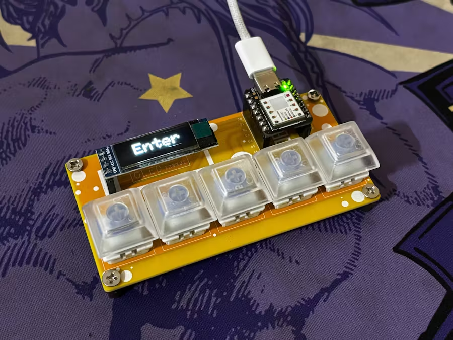
To add some custom flair, we built a volume control knob from scratch. It’s based on Seeed Studio's XIAO SAMD21 microcontroller and utilizes the HID protocol to manage system volume.
The enclosure and internal components were designed in Fusion 360 and brought to life using an Ender 3 3D printer. In this article, we’ll walk through a quick build guide for the project — so let’s jump right in.
Materials Required
Raspberry Pi 5 (4GB) with an attached cooler
Official Raspberry Pi M.2 HAT
Custom-designed PCBs
3D-printed components
Potentiometer
XIAO SAMD21 Microcontroller
NVMe SSD (Gen 3x4)
M2 Screws
M3 PCB Standoffs
Design Concept
We began the design process in Fusion 360, where we carefully modeled the keyboard. This involved taking precise measurements of the keyboard’s dimensions, key layout, and overall structure.
Creating an accurate model was crucial, as it allowed us to design a frame that fits perfectly around the keyboard.
At the back, we added three custom keyboard holder components designed to secure the keyboard membrane in place. These holders are fastened using the existing screw bosses built into the keyboard.
The main structure of the model is divided into two key sections: the frame and the holder assembly. The frame itself is split into left and right segments.
To connect the frame parts, we used two logo elements and secured everything with four M2 screws.
One of the holders is dedicated to mounting the Raspberry Pi, while the other supports the volume control circuit.
For a unique aesthetic touch, we included a stylized accent piece inspired by the Capsule Corp logo from the Dragon Ball series—adding a subtle sci-fi vibe to the build. Once the design was complete, we exported it as mesh files for 3D printing.
The print settings used were a 0.6mm nozzle, 20% infill, and a 0.2mm layer height. For materials, we chose clear PLA for the frame, orange PLA for the keyboard holders, and grey PLA for the Raspberry Pi holder.
XIAO HID Volume Knob
The volume control knob circuit was designed around a potentiometer connected to an XIAO SAMD21 microcontroller. In the schematic, a CON3 JST connector is used, which interfaces with GND, D0, and VCC. This connector is where the potentiometer is attached to the XIAO.
We also included another connector, CON2, which links to the XIAO’s VCC and GND for additional connectivity options.
Since the XIAO is powered directly via a USB connection to the Raspberry Pi, there’s no need for separate batteries or a dedicated power supply circuit.
For the PCB layout, we used precise measurements from our CAD design, including mounting hole placements and the location of the microcontroller.
To give the board a more polished and custom feel, we added decorative graphics on both the top and bottom layers of the PCB.
The PCB was designed, Gerber files were generated, and the board was manufactured using a custom color scheme—featuring a black silkscreen with a white solder mask. The boards were delivered within a week and came out with great quality at a budget-friendly price.
This streamlined process allowed us to quickly move from concept to a functional, well-integrated volume knob controller, ready to be embedded in the final setup.
PCB Assembly
Assembling the PCB was fairly straightforward, thanks to its through-hole design and absence of surface-mount components.
The process began with placing two CON7 header pin sockets onto the board. Once those were secured, we added the CON3 UC203 connector in its designated position.
Using a soldering iron, we carefully soldered the pads for both the CON7 headers and the CON3 connector.
After the soldering was complete, we aligned the XIAO SAMD21 microcontroller with the installed CON7 header pins and plugged it in. Finally, the potentiometer’s wire harness was connected to the CON3 socket, completing the assembly.
CODE
Here's the sketch that we used in this project to control the PC's volume, and it utilizes the HID protocol using an XIAO microcontroller. This was because of the microchip's SAMD21G18 inside the XIAO SAMD21.
int val = 0;
int previousval = 0;
int val2 = 0;
void setup() {
Consumer.begin(); //initialize computer connection
delay(1000); //wait for computer to connect
for(int a = 0; a < 52; a++) {
Consumer.write(MEDIA_VOLUME_DOWN); //set the volume to 0
delay(2);
}
}
void loop() {
val = analogRead(D0); //read potentiometer value
val = map(val, 0, 1023, 0, 101); //map it to 102 steps
if(REVERSED) {
val = 101 - val;
}
if(abs(val - previousval) > 1) { //check if potentiometer value has changed
previousval = val;
val /= 2; //divide it by 2 to get 51 steps
while(val2 < val) {
Consumer.write(MEDIA_VOLUME_UP); //turn volume up to appropiate level
val2++;
delay(2);
}
while(val2 > val) {
Consumer.write(MEDIA_VOLUME_DOWN); //turn volume down to appropiate level
val2--;
delay(2);
}
}
delay(301);
}
Frame Assembly
Before starting the main assembly, we connected the two halves of the frame and secured them from the input side using a custom “Pi1000” logo piece.
This logo part is fixed in place with four M2 screws, helping to align and stabilize the connection between the left and right sections of the frame.
On the opposite side, we attached a secondary logo piece, also fastened using M2 screws.
These two logo components serve dual purposes: structurally, they bring the two frame halves together into a unified chassis, and aesthetically, they give the frame a more finished, visually appealing look.
Keyboard Breakdown
For this project, we selected a small membrane keyboard that was both affordable and appropriately sized for the build.
Membrane keyboards operate using pressure pads instead of individual mechanical switches. These pads are part of a flexible PCB layered with conductive traces that connect to the keyboard’s driver board.
The main driver PCB typically includes a black epoxy blob — a circuit-on-board (COB) — which houses the microcontroller chip.
To prepare the keyboard for integration, we disassembled it by removing the plastic key cover (top layer), the inner membrane layer composed of three flexible PCBs, and the plastic bottom casing. Only the flexible PCB membrane and the top key layer were retained for use in our custom build.
Keyboard Assembly

To begin reassembling the keyboard, we first installed the Flex PCB Holder at the back of the key layer.
This holder consists of three custom 3D-printed parts designed to gently press down and stabilize the membrane PCB layer, ensuring that key presses register correctly without the need for the original back casing.
Each holder is secured with M2 screws, locking the membrane in place.
With the holders installed, the keyboard can now function properly without its original bottom cover. This updated configuration is cleaner and better suited for the integrated design of the Pi1000.
Raspberry Pi 5
For this build, we’re using the 4GB version of the Raspberry Pi 5. It features a Broadcom BCM2712 2.4GHz quad-core 64-bit Arm Cortex-A76 processor and uses LPDDR4X-4267 SDRAM, available in configurations ranging from 1GB to 8GB.
The board also comes equipped with the new VideoCore VII GPU, making it well-suited for handling 4K video playback and emulation tasks. Impressively, it supports dual 4K displays for a more immersive setup.
One of the most exciting additions in the Raspberry Pi 5 is the PCIe 2.0 x1 interface, which finally allows for the direct use of PCIe-compatible devices such as SSDs—or even GPUs through custom adapters.
Adding the Cooler to the Raspberry Pi 5
To ensure proper cooling, we began by removing the protective film from the thermal paste on the cooler. The cooler was then aligned and placed directly over the processor.
It attaches to the Raspberry Pi using built-in mounting holes and is secured via plastic snap locks. Once in place, we connected the cooler’s JST connector to the corresponding port on the Raspberry Pi 5.
With the cooler installed, the setup was ready for the addition of the M.2 HAT shield.
Raspberry Pi 5 – M.2 HAT and OS Setup

In our setup, we used the official Raspberry Pi M.2 HAT, which supports M-Key SSDs in the 2230 and 2242 form factors. Since we already had a 2280-sized SSD, we designed a custom adapter to extend the mounting area, allowing it to fit securely onto the HAT.
We installed an Ant Esports 690 Neo Pro NVMe PCIe Gen 3.0 x4 SSD, capable of read/write speeds up to 1600 MB/s and 1100 MB/s respectively.
To install Raspberry Pi OS on the SSD, we followed a widely used method that involves preparing the SSD using a PC and a USB adapter. The OS image is written using Raspberry Pi Imager. Alternatively, you can first install the OS on an SD card, boot from it, and then clone the installation onto the SSD.
In our case, we opted for the cloning method. Before the Pi can boot from an external SSD, the PCIe interface must be enabled. This is done by editing the config.txt file on the boot partition and adding the following lines:
# Note: You could also just add the following (it is an alias to the above line)
# dtparam=nvme
# Optionally, you can control the PCIe lane speed using this parameter
# dtparam=pciex1_gen=3
To clone the SD Card into the SSD, we first check if the Raspberry Pi is reading the SSD, which can be done by running lsblk Next, we run rpi-clone, which is a shell script for cloning a Raspberry Pi booted source disk developed by Jeff Geerling.
# Clone to the NVMe drive (usually nvme0n1, but check with `lsblk`).
sudo rpi-clone nvme0n1
Pi Holder Assembly


With the Raspberry Pi fully prepared, we moved on to mounting it onto the custom 3D-printed Pi holder. The board is aligned with the holder and secured using four M3 bolts along with matching M3 PCB standoffs.
Once the Pi is in place, the M.2 Shield is mounted directly on top of it, also secured using four M3 bolts. Afterward, the PCIe flex cable is connected — one end to the Raspberry Pi’s PCIe port, and the other to the M.2 HAT.
Installing the Pi Holder into the Keyboard Frame
To integrate the Pi assembly into the larger frame, we placed it above the designated mounting points inside the keyboard-frame structure. The entire unit was then fastened in place using four M2 screws, locking it securely to the main chassis.
After this, we connected the keyboard’s USB output to one of the USB 2.0 ports on the Raspberry Pi, completing the keyboard-to-Pi connection.
Volume Knob Holder Assembly
For the volume control module, the PCB was first placed onto its 3D-printed holder and fixed in place with four M2 screws.
The potentiometer was then installed by fitting it into the dedicated hole located on the left side of the keyboard frame. Once aligned, the PCB holder was secured to the frame using four additional M2 screws.
To finalize the assembly, a USB Type-C data cable was used to connect the XIAO microcontroller to the Raspberry Pi, with the cable plugged into one of the Pi’s USB 2.0 ports.
Final Assembly
The last step in the assembly involves attaching the USB side cover. This cover is positioned on the left side of the frame and secured in place using an M3 nut and bolt.
Next, the Capsule Corp badge is attached to the front of the frame, near the Raspberry Pi’s HDMI ports. We used adhesive to firmly attach the badge, giving the project its signature sci-fi touch.
Result
The end result of this project is a fully functional Raspberry Pi PC housed inside a keyboard, running Raspberry Pi OS. This setup is notably faster than the Raspberry Pi 400 Keyboard PC, thanks to the upgrade to the Raspberry Pi 5.
We began by customizing a commercially available keyboard, modifying it to house the Raspberry Pi and its components. The Raspberry Pi 5 is directly connected to the keyboard, and a custom volume control PCB, utilizing an XIAO SAMD21 microcontroller, was also integrated into the design.
The inclusion of an NVMe SSD, replacing the standard SD card, significantly boosts performance, making the system far more responsive than the typical Raspberry Pi 5 setup.
Benchmarks: Geekbench 6 Score
To assess the performance of our setup, we began by installing Geekbench 6, a benchmarking tool that provides a detailed overview of the CPU and memory performance.
We used Pi Apps, a platform with optimized applications for Raspberry Pi, to install Geekbench:
Install Pi Apps:
Once installed, Geekbench was run from the terminal. The results showed a single-core score of 824 and a multi-core score of 1836. These are solid scores for an SBC (Single Board Computer), especially one with low power consumption.
For context, the Intel i9-13900KS, a high-end desktop CPU, scores 3106 in single-core and 21816 in multi-core benchmarks, owing to its 24-core, 32-thread architecture.
Additionally, the Radxa ROCK 5A, another ARMv8-based SBC with a similar core structure (1 core, 8 threads), scores 878 in single-core and 3082 in multi-core, outperforming the Raspberry Pi 5 in both categories.
Despite these comparisons, our Raspberry Pi 5 setup, with an NVMe SSD, offers a significant performance boost over the standard SD card-based setups, making it a powerful and compact solution for everyday tasks and development.
Games: Minecraft
In addition to the Geekbench score, we tested the Raspberry Pi 5 with the Minecraft Bedrock edition. The game ran consistently at 60–65 frames per second, which is impressive for a single-board Linux computer.
Considering the hardware, the performance was smooth and responsive, with a fluid framerate that enhanced the overall gaming experience. Minecraft played exceptionally well, providing a quick and seamless gameplay experience.
Emulation: PSP
After playing Minecraft, we installed the PPSSPP emulator from Pi Apps and tried running Tekken 6. We were able to play it for over an hour without any performance issues, demonstrating the Pi's capability to handle emulation smoothly.
We connected an Xbox controller via USB to the Raspberry Pi, as we encountered issues with Bluetooth connectivity. Despite this, the emulator worked flawlessly, and Tekken 6 ran without a hitch, providing a smooth and enjoyable experience.
Conclusion and Version 2
Finally, we launched Chrome and played a 4K YouTube video to test the Raspberry Pi 5’s performance. The CPU utilization stayed below 20%, which was impressive. Thanks to the advanced VideoCore VII GPU, the Pi 5 delivers better 3D graphics performance compared to the previous Pi models, making it capable of handling demanding tasks with ease.
When compared to the Raspberry Pi 4, the Pi 5 offers a significant leap in performance, connectivity, and overall features. It’s a far more powerful and versatile platform for a wide variety of applications.
The result of this project is a fully functional Pi5-based PC encased inside a keyboard. All that’s needed is power and a display connection to make it run.
In the next iteration (Version 2), we plan to address some design issues, such as the thick frame, which resulted from certain mechanical constraints. The new version will feature a thinner design, as we plan to build the keyboard from scratch, optimizing space and improving the overall form factor.
If you have any questions or need help with this project, feel free to leave a comment. I’ll be happy to assist!
Thanks for following along, and stay tuned for my next project