Ever seen those flashing police lights and wondered how they work? In this beginner-friendly project, we’ll replicate a similar flashing effect using just a few components: red, blue, and white LEDs, an Arduino Uno, a breadboard, and some jumper cables. This project is a great way to dive into Arduino programming and understand how to control multiple outputs with timing. Whether you’re building a model vehicle, experimenting with light patterns, or just starting out with microcontrollers, this project is quick, fun, and educational.
This project is perfect for Arduino beginners who want to get hands-on with real circuits and LED control. Follow these steps to build your very own police-style LED flasher with Red, White, and Blue LEDs.
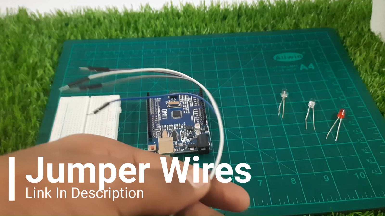
Step 1: Gather All Components
You’ll need the following parts:
Arduino Uno
Breadboard
Red LED
White LED
Blue LED
Jumper wires (male-to-male)
3x Resistors (220–330 ohms)
USB cable to upload code from your computer
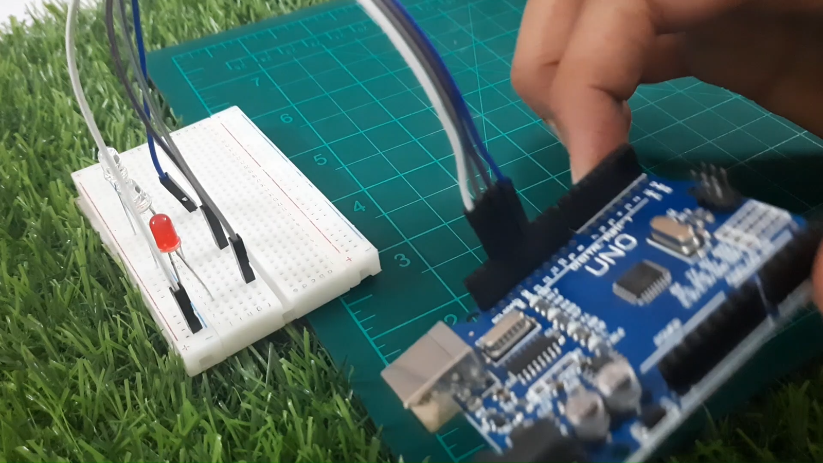
Step 2: Connect the LEDs
Let’s wire each LED to its respective pin on the Arduino.
Red LED → Pin 13
White LED → Pin 12
Blue LED → Pin 11
Connect the cathode (short leg) of all LEDs to the GND rail on the breadboard
Connect GND rail to GND on Arduino
Place one resistor in series with each LED (on the anode side)
Tip: Always use resistors to avoid damaging the LEDs.
Step 3: Understand the Code in Detail
This project uses a simple Arduino sketch to turn LEDs ON and OFF in a pattern that simulates police lights. Let’s break down the code and explain each part so you know exactly what’s happening and how to tweak it.
 The Setup Block
void setup() {
pinMode(13, OUTPUT);
pinMode(12, OUTPUT);
pinMode(11, OUTPUT);
}
This runs once when your Arduino powers up.
pinMode(pin, OUTPUT); tells the Arduino that pins 13, 12, and 11 will control outputs — in this case, LEDs.
 You can change the pins here if you're using different ones for your LEDs.
The Loop Block
void loop() {
digitalWrite(13, HIGH); // RED ON
digitalWrite(12, HIGH); // WHITE ON
digitalWrite(11, LOW); // BLUE OFF
delay(80);
digitalWrite(pin, HIGH); turns the LED ON
digitalWrite(pin, LOW); turns the LED OFF
delay(80); pauses the code for 80 milliseconds before moving to the next step
In this first part:
RED and WHITE LEDs turn ON
BLUE is OFF
The pattern stays for 80ms
digitalWrite(13, LOW);
digitalWrite(12, HIGH);
digitalWrite(11, LOW);
delay(80);
Now:
Only WHITE LED remains ON
RED and BLUE are OFF
Another short pause
This creates a flashing "pulse" with emphasis on the WHITE LED.
---
digitalWrite(13, HIGH);
digitalWrite(12, HIGH);
digitalWrite(11, LOW);
delay(0);
RED and WHITE are ON again, no delay this time (makes it look like a flicker)
---
digitalWrite(13, LOW);
digitalWrite(12, HIGH);
digitalWrite(11, HIGH);
delay(80);
WHITE and BLUE ON
RED OFF
This changes the light effect, simulating the opposite end of a strobe.
---
digitalWrite(13, LOW);
digitalWrite(12, HIGH);
digitalWrite(11, LOW);
delay(80);
And again, we flash WHITE only.
---
digitalWrite(13, LOW);
digitalWrite(12, HIGH);
digitalWrite(11, HIGH);
delay(0);
}
Ends the loop with WHITE and BLUE ON again — but instantly moves back to the start.
 How to Change the Flash Pattern
Want a slower flash? Just increase the delay values. For example:
delay(300); // 300ms = slower
Want each LED to blink one-by-one? Try this simple loop:
void loop() {
digitalWrite(13, HIGH); delay(200);
digitalWrite(13, LOW);
digitalWrite(12, HIGH); delay(200);
digitalWrite(12, LOW);
digitalWrite(11, HIGH); delay(200);
digitalWrite(11, LOW);
}
 Experiment: Try using different delays for each LED to create rhythmic or random police-like effects.
---
Bonus Tip: Use millis() Instead of delay()
If you want more advanced control without freezing the program, you can replace delay() with millis() for non-blocking flashing patterns. But for now, delay() is easiest for beginners.
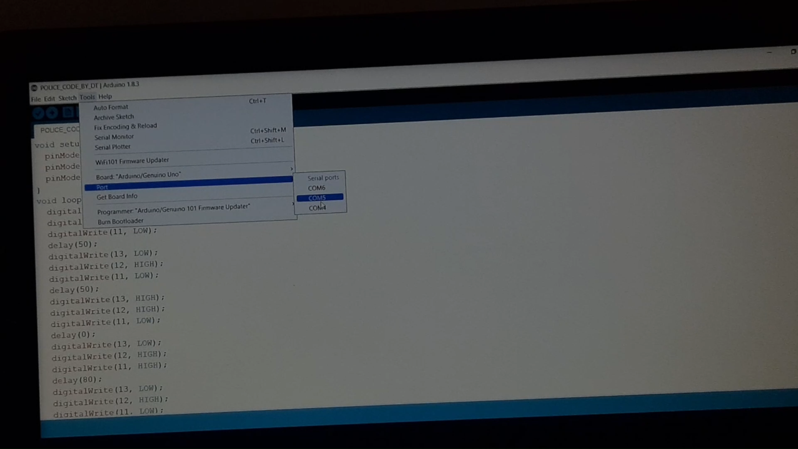
 Step 4: Upload the Code
 Step 4: Upload the Code
Open the Arduino IDE on your computer, connect the Arduino Uno, And Select the Valid Com Port and upload the code below:
void setup() {
pinMode(13, OUTPUT);
pinMode(12, OUTPUT);
pinMode(11, OUTPUT);
}
void loop() {
digitalWrite(13, HIGH);
digitalWrite(12, HIGH);
digitalWrite(11, LOW);
delay(80);
digitalWrite(13, LOW);
digitalWrite(12, HIGH);
digitalWrite(11, LOW);
delay(80);
digitalWrite(13, HIGH);
digitalWrite(12, HIGH);
digitalWrite(11, LOW);
delay(0);
digitalWrite(13, LOW);
digitalWrite(12, HIGH);
digitalWrite(11, HIGH);
delay(80);
digitalWrite(13, LOW);
digitalWrite(12, HIGH);
digitalWrite(11, LOW);
delay(80);
digitalWrite(13, LOW);
digitalWrite(12, HIGH);
digitalWrite(11, HIGH);
delay(0);
}
---
Step 5: Power it Up!
 Step 5: Power it Up!
Plug in the Arduino using a USB cable
Once the code uploads, the LEDs will start blinking in a repeating police-style pattern

 What You’ve Learned
How to control LEDs using digital pins
Using pinMode() and digitalWrite() functions
Creating timed patterns with delay()
Building a functional breadboard circuit
And that’s it! You’ve just built your very own police light flasher using an Arduino Uno and a few basic components.  This simple project is a fantastic starting point for anyone new to electronics and microcontroller programming.
Not only did you learn how to wire up LEDs and control them through digital pins, but you also explored how to create custom flashing patterns using delays — a fundamental concept in Arduino projects. With just a few lines of code and creative tweaks, you can now modify the light effects however you like!
Feel free to experiment further:
Try using RGB LEDs to mix colors
Add buzzers or sirens for extra effect
Or use millis() instead of delay() for non-blocking code in future projects
Projects like this are the building blocks of your journey into embedded systems and robotics — and trust me, it only gets more exciting from here! 
If you tried this build, share your results or mods in the comments or tag me on Instagram @drab_tech! I love seeing your
creative takes.