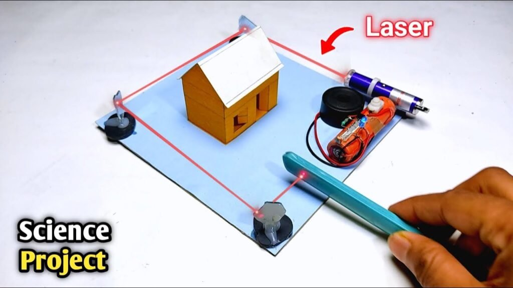
Creating a Laser + LDR Security Alarm System is a simple and effective DIY electronics project. It uses a laser pointer, LDR (Light Dependent Resistor), LED, diode, resistor, and a buzzer or other alarm system to detect when a laser beam is interrupted — commonly used in basic intrusion or object detection systems.
🔧 Components Required:
| Component | Specification |
|---|---|
| LDR (Light Dependent Resistor) | 1x |
| Laser pointer/module | Red laser, 5V |
| Resistor | 10kΩ, 220Ω |
| Diode | 1N4007 or similar |
| LED | Any color |
| Buzzer | 5V (optional) |
| Transistor | BC547 or 2N2222 (to drive LED or buzzer) |
| Power Supply | 5V Battery or Adapter |
| Breadboard & Wires | For prototyping |
⚙️ Working Principle:
Laser continuously shines on the LDR.
The LDR has low resistance in light and high resistance in darkness.
When someone passes through the laser beam, it breaks — causing a sudden change in LDR’s resistance.
This change is used to trigger a transistor circuit which turns ON an LED or buzzer.
🛠️ Circuit Diagram Overview:
[Power Supply +5V]

|

[Laser Diode] ---> shines on ---> [LDR]---+--[10kΩ]---> GND

|

[Transistor Base via 220Ω]

|

[Transistor Collector -> LED/Buzzer -> GND]
🧪 Step-by-Step Instructions:
🔹 Step 1: Set Up the Laser
Place the laser in a fixed position so it shines directly on the LDR.
Ensure alignment is tight so even small movements break the beam.
🔹 Step 2: Connect LDR Circuit
Connect one side of the LDR to Vcc (5V).
Connect the other side of the LDR to a 10kΩ resistor, and connect the other end of the resistor to GND.
The junction point between LDR and the resistor goes to the base of an NPN transistor via a 220Ω resistor.
🔹 Step 3: Add Diode Protection
Place a diode (1N4007) in reverse bias between the transistor’s collector and emitter to protect from reverse voltage spikes.
🔹 Step 4: Connect the LED or Buzzer
Connect an LED or buzzer in series with the collector of the transistor.
Connect the emitter to GND.
The collector goes to +5V through the LED/buzzer.
🔹 Step 5: Power Up the Circuit
Use a 5V battery pack or USB power supply.
When the laser beam is aligned and unbroken, the transistor stays off.
When the beam is interrupted, LDR resistance increases, voltage drops at the base — transistor turns ON, activating LED or buzzer.
💡 Tips for Better Performance:
Use a tube or casing for LDR to avoid ambient light.
Secure laser with clamps or mounts for stability.
You can extend this to trigger a camera or send a signal to a microcontroller like Arduino.
🧠 Applications:
Doorway intruder alert
Object counting system
DIY laser security perimeter
Tripwire for home safety projects
📸 Add Visuals (for your site):
Circuit Diagram
Breadboard Layout
Laser-LDR Alignment Photo
Working Demo Image or Video
✅ Summary:
This Laser + LDR Security Alarm System is a great beginner-level electronics project. It teaches the fundamentals of light sensors, transistor switching, and basic security systems — all with cheap, easily available components.
Would you like me to turn this into an SEO-optimized upload post for your platform Tinkerzy with a proper SEO title, meta description, tags, featured image, and internal links?
You said:
ChatGPT said:
Sure! Here’s a complete blog-style guide based on the “Smart Glasses for Blind Without Arduino” project — fully formatted for upload on your Tinkerzy platform, including step-by-step instructions, SEO elements, and visual placeholder spots.
Smart Glasses for Blind Without Arduino – Third Eye for the Visually Impaired | School Science Project
SEO Title: Smart Glasses for Blind Without Arduino – Third Eye for Visually Impaired
Meta Description: Learn how to make smart glasses for blind people using NE555 IC, ultrasonic sensor, and basic components — no Arduino needed! A simple, affordable Inspire Award project with step-by-step guide.
Focus Keyword: Smart Glasses for Blind Without Arduino
🧠 Project Overview
This Smart Glasses for Blind Without Arduino project acts as a third eye for visually impaired people. Using an ultrasonic sensor and NE555 timer IC, these glasses detect nearby obstacles and alert the wearer with a buzzer sound. This project is Arduino-free, affordable, and perfect for school exhibitions or the Inspire Award competition.
📦 Components Required
📲 Circuit Diagram
🔗 View Circuit Diagram on Instagram
📌 Note: Refer to the wiring image for detailed connection overview.
🛠️ How to Make Smart Glasses for Blind (Without Arduino)
🔹 Step 1: Prepare the Glass Frame
Use a simple sunglass or spectacle frame.
Remove the lenses and make space for attaching sensors and electronics.
🔹 Step 2: Mount the Ultrasonic Sensor
Place the ultrasonic sensor at the front center of the frame.
Secure it using hot glue or double-sided tape.
This sensor will detect obstacles in front of the user.
🔹 Step 3: Build the NE555 Circuit
Use a breadboard or small PCB to connect the components:
NE555 timer configured in monostable mode.
Connect 10KΩ and 1KΩ resistors, capacitors as per circuit diagram.
The trigger pin (pin 2) receives signal from the ultrasonic sensor.
🔹 Step 4: Connect the Output to Buzzer
Output pin (pin 3) of NE555 IC is connected to a 5V buzzer.
When an obstacle is detected, the NE555 timer activates the buzzer.
Use a tactile switch to turn the circuit on/off manually.
🔹 Step 5: Power Supply
Use a 3.7V battery to power the entire circuit.
Connect battery output to the VCC and GND of the system via switch.
Optionally, use a charging module (TP4056) if you want rechargeable glasses.
🔹 Step 6: Final Assembly
Secure all components neatly on the glasses frame.
Use heat shrink tubing or insulation tape to cover exposed wires.
Make sure the circuit is lightweight and wearable.
⚙️ How It Works
The ultrasonic sensor continuously checks for obstacles.
When any object comes close (within 1–2 meters), it triggers the NE555 timer.
The NE555 sends a pulse to activate the buzzer.
The user hears a buzzing sound — acting as an alert for nearby objects.
💡 Applications
Blind or visually impaired assistance device
Obstacle detection for robotics
Walking aid enhancement tool
Science exhibition / Inspire Award project
📸 Add Visuals (For Website Upload)
🔹 Featured Image: Glasses with sensor module
🔹 Circuit Diagram: Clean version of the NE555 circuit
🔹 Wiring Image: Real-life connection photo
🔹 Step-by-step build photos (optional)
🔹 Working Demo Video (YouTube embedded)
🔗 Related Projects
🧩 Tags:
Smart Glasses, Inspire Award Project, Science Exhibition, Blind Aid, DIY Electronics, NE555 IC Projects, No Arduino, Simple School Project, PendTech
📌 Final Thoughts
This Third Eye for the Blind is an excellent low-cost alternative to smart vision aids. Without using any microcontroller like Arduino, you can still build a fully functional obstacle detector that improves mobility for visually impaired people.
Would you like me to design a Canva-based featured image or pin diagram for this post?
Let me know if you’d like a downloadable .txt or WordPress-optimized plain text version too!
You said:
ChatGPT said:
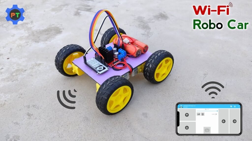
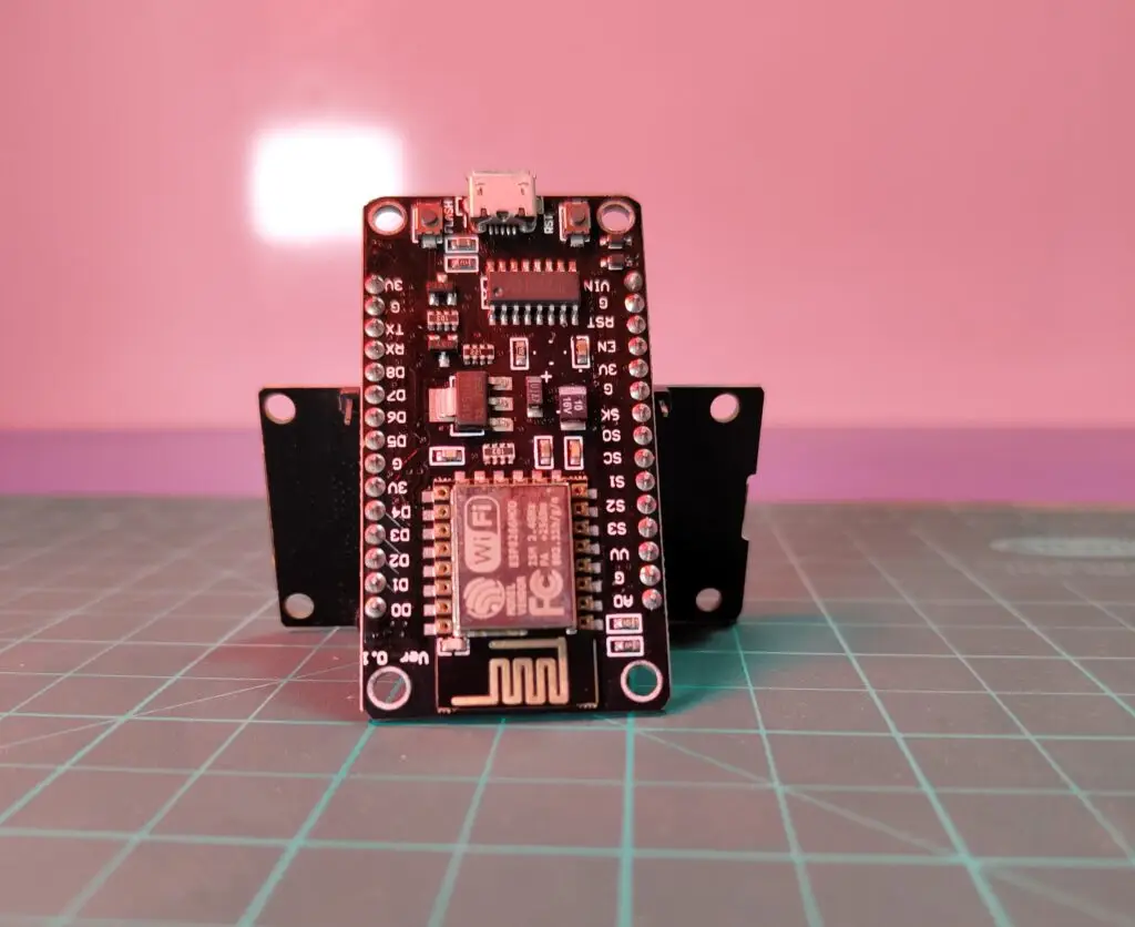
Absolutely! Here’s the full blog-style project post for your website Tinkerzy, based on the “Wi-Fi Control Robot Car using NodeMCU ESP8266” video. It includes step-by-step instructions, SEO elements, and placeholders for visuals.
Wi-Fi Control Robot Car Using NodeMCU ESP8266 | Smartphone Controlled DIY Project
SEO Title: Wi-Fi Control Robot Car Using NodeMCU ESP8266 – Mobile Controlled Car DIY Guide
Meta Description: Learn how to build a Wi-Fi-controlled robot car using NodeMCU ESP8266, L298N motor driver, and your smartphone. Full step-by-step tutorial with code, circuit diagram, and remote control app setup.
Focus Keyword: Wi-Fi Control Robot Car Using NodeMCU
🧠 Project Overview
This Wi-Fi Controlled Robot Car project is a smart and fun DIY build that uses a NodeMCU ESP8266 microcontroller to control a car wirelessly using a mobile phone over Wi-Fi. You’ll be able to move your car forward, backward, left, and right using a custom mobile app or browser-based interface.
Perfect for students, hobbyists, or science exhibition entries, this project is fully functional and simple to assemble!
📦 Components Required
| Component | Buy Link |
|---|---|
| NodeMCU ESP8266 | Buy Here |
| L298N Motor Driver | Buy Here |
| Gear Motors & Wheels (x4) | Buy Here |
| Li-ion Batteries (18650 x2) | Buy Here |
| Power Switch | Local electronics store |
| Chassis Board | Optional (or make with cardboard/acrylic) |
| Jumper Wires | Required for all connections |
| Battery Holder (2-cell) | Optional for better wiring |
📲 Circuit Diagram
🖼️ Insert a labeled connection diagram showing NodeMCU to L298N and motors.
📌 If you have a real wiring image or breadboard layout, insert it here for clarity.
🛠️ How to Make Wi-Fi Control Robot Car
🔹 Step 1: Mount Motors on Chassis
Fix 4 gear motors to your car chassis.
Attach wheels to each motor shaft.
Secure using glue or screws (as per your material).
🔹 Step 2: Connect Motors to L298N Motor Driver
Connect the left side motors to OUT1 and OUT2 of the motor driver.
Connect the right side motors to OUT3 and OUT4.
Connect 12V and GND pins of L298N to the battery pack.
Connect ENA and ENB to 5V via jumpers (or control them via code for speed control).
🔹 Step 3: Connect NodeMCU to Motor Driver
IN1 → D1 (GPIO5)
IN2 → D2 (GPIO4)
IN3 → D3 (GPIO0)
IN4 → D4 (GPIO2)
GND → Common Ground
5V → Power from motor driver’s onboard regulator
🔹 Step 4: Power Setup
Use two 3.7V 18650 batteries to power the motor driver (around 7.4V).
NodeMCU gets power from the 5V regulator on L298N.
Add a switch between battery and L298N to control power.
💻 Step 5: Upload the Code
🔗 Programming Code – Google Drive Link
Use Arduino IDE or ArduinoDroid App on Android.
Select board: NodeMCU 1.0 (ESP-12E Module)
Upload the code via USB.
The code sets up the NodeMCU as a web server with control buttons.
📱 Step 6: Control via Smartphone
Option 1: Web Browser
Connect your phone to the Wi-Fi hotspot created by NodeMCU.
Open the IP address (e.g., 192.168.4.1).
Use on-screen buttons to move the car.
Option 2: Android App
🔗 Remote Control App – Google Drive
📸 Add Visuals (For Your Blog Upload)
🔹 Featured Image: Smart robot car photo with NodeMCU on top
🔹 Wiring Diagram
🔹 Screenshot of App Interface
🔹 Programming Code UI from Arduino IDE
🔹 Optional: Demo GIF or embedded YouTube video
🧠 How It Works
NodeMCU ESP8266 creates a local Wi-Fi network or connects to your router.
The car is controlled via HTTP commands sent from the mobile browser or app.
The motor driver module interprets those signals to drive motors in desired directions.
🧩 Applications
Wi-Fi-controlled car for fun or surveillance
IoT smart automation models
Robotics for beginners
School or college exhibition project
🔗 Related Projects
🏷️ Tags:
Wi-Fi Robot Car, NodeMCU ESP8266, Mobile Controlled Robot, L298N Motor Driver, DIY Robotics, Science Project, PendTech, IoT Car, Remote Control Car
✅ Final Thoughts
This Wi-Fi-Controlled Robot Car using NodeMCU is an impressive combination of IoT and robotics. It’s ideal for tech lovers who want to explore remote control, embedded systems, and real-time connectivity — all without the complexity of Bluetooth pairing!
Would you like me to design a Canva cover image, pinout diagram, or provide the WordPress-ready version of this blog?
Let me know what you’d like next!
You said:
ChatGPT said:
Absolutely! Here’s the blog-style post for the Automatic Fire Fighting Robot (Without Arduino) project, optimized for your Tinkerzy platform with all SEO elements, detailed steps, and placeholders for visuals.
Automatic Fire Fighting Robot Without Arduino | DIY Science Project
SEO Title: How to Make an Automatic Fire Fighting Robot Without Arduino – DIY Science Project
Meta Description: Learn how to build a simple automatic fire extinguisher robot car without Arduino using IR photodiode, relay, transistor, and gear motors. Step-by-step guide, wiring diagram, and components list included.
Focus Keyword: Automatic Fire Fighting Robot Without Arduino
🧠 Project Overview
This Automatic Fire Fighting Robot is a fantastic school-level science project that detects fire using an IR photodiode sensor and automatically moves toward the fire to extinguish it using a fan or LED-based indicator system.
What makes it even more interesting? It works without any microcontroller like Arduino! It uses basic electronics components to build a fire-responsive bot using just sensors, transistors, and relays.
Perfect for Inspire Award projects, exhibitions, and students wanting to learn electronics in a practical way.
📦 Components Required
| Component | Buy Link |
|---|---|
| IR Photodiode (Receiver) | Buy Here |
| BC547 NPN Transistor | Buy Here |
| Resistors (220Ω, 1kΩ, 10kΩ) | Buy Here |
| LED (Any color) | Buy Here |
| 1N4007 Diode | Buy Here |
| 5V Relay | Buy Here |
| 3.7V Li-ion Battery (x2) | Buy Here |
| Gear Motors (x4) | Buy Here |
| Power Switch | Local electronics store |
| Wires, Battery Holder, Chassis, Glue, etc. | DIY toolkit |
📲 Circuit Diagram
🖼️ Insert a clean labeled circuit diagram showing connections between photodiode → transistor → relay → motors.
📌 Instagram Circuit Diagram Reference
🛠️ How to Make the Automatic Fire Fighting Robot
🔹 Step 1: Prepare the Chassis
Fix all four gear motors to the base (cardboard, acrylic, or plastic chassis).
Attach wheels to the motor shafts.
Connect the motors in parallel pairs (left & right) to allow forward/backward motion.
🔹 Step 2: IR Sensor Setup
Connect the IR photodiode in a voltage divider configuration with a 10kΩ resistor.
The sensor will detect infrared light emitted by flames.
Important: It only works well indoors, as sunlight contains IR light that may interfere.
🔹 Step 3: Build the Control Circuit
Use the BC547 transistor as a switch to control the 5V relay.
When the IR sensor detects fire, it sends a signal to the base of the transistor.
The transistor then powers the relay module, which can turn on:
A fan motor (to simulate extinguishing)
OR the car motors (to move the robot toward the fire)
🔹 Step 4: Motor & Relay Connection
Connect the relay’s output to control power to the gear motors.
When activated, the motors start moving toward the detected flame.
Optionally, add a fan or a bright LED as a visual extinguisher.
🔹 Step 5: Power Setup
Connect two 3.7V Li-ion batteries in series (~7.4V).
Use a switch to control the power.
Make sure all grounds are common across components.
⚠️ Important Notes
Works best indoors to avoid false IR triggers from sunlight.
Make sure transistor and relay values are accurate.
Ensure motor load doesn’t exceed relay rating (use small DC motors).
🧩 How It Works
The IR sensor detects infrared radiation (heat) from fire.
When triggered, it sends a small signal to the BC547 transistor, acting like a gate.
The transistor powers the relay, which switches on the motor/fan system.
The robot automatically moves toward the fire or turns on an extinguisher simulation.
📸 Visual Media Suggestions
🔹 Featured image: Robot chassis with IR sensor and relay module visible
🔹 Circuit diagram with pin labels
🔹 Close-up photo of relay and transistor connection
🔹 Action shot of robot responding to candle flame
🧠 Applications
School-level science exhibitions
Inspire Award competitions
Fire-detection and automation prototypes
Learning real-world transistor and relay logic
🔗 Related DIY Projects
🏷️ Tags:
Fire Fighting Robot, No Arduino Project, Relay Based Robot, IR Flame Detection, DIY Science Project, Inspire Award, Fire Extinguisher Robot, PendTech, School Exhibition Robot
✅ Final Thoughts
This Automatic Fire Fighting Robot Without Arduino is proof that you don’t always need microcontrollers for smart automation. A clever use of IR sensors, transistors, and relays can create intelligent robots even with simple electronics knowledge.
💡 Want this project as a downloadable PDF, featured image design, or embed code for WordPress?
Let me know, and I’ll prep it for your next upload!
You said:
ChatGPT said:
Absolutely! Here’s the full SEO-optimized project post for the Automatic Accident Avoiding Car using Arduino, formatted for your Tinkerzy platform with structured headings, detailed steps, keyword optimization, and media placeholders.
Automatic Accident Avoiding Car Using Arduino | DIY Smart Robot Car
SEO Title: How to Make an Automatic Accident Avoiding Car Using Arduino – DIY Smart Car Science Project
Meta Description: Learn how to build an automatic accident avoiding car using Arduino and ultrasonic sensor. Perfect for school science projects and exhibitions. Complete tutorial with circuit diagram and code.
Focus Keyword: Automatic Accident Avoiding Car Using Arduino
🧠 Project Overview
In this fun and educational DIY, we’ll build a Smart Accident Avoiding Car using Arduino UNO and an ultrasonic sensor. This self-driving robot car can detect obstacles in its path and change direction automatically to avoid collisions.
Whether you’re participating in a science exhibition, school project, or just exploring the basics of robotics and automation, this is a perfect beginner-level Arduino project that shows real-world applications of sensors and microcontrollers.
📦 Components Required
📲 Circuit Diagram
🖼️ Insert labeled circuit diagram with:
Ultrasonic sensor connected to Arduino (VCC, GND, Trig, Echo)
Motors connected via relay or motor driver
Buzzer connected to a digital pin
Power supply connections
💾 Arduino Code
📄 Download the full Arduino code:
Automatic Car Code (Google Drive)
Or embed this link inside a code block:
// Basic obstacle avoiding logic

const int trigPin = 9;

const int echoPin = 10;

const int motorLeft = 3;

const int motorRight = 4;
void setup() {
pinMode(trigPin, OUTPUT);
pinMode(echoPin, INPUT);
pinMode(motorLeft, OUTPUT);
pinMode(motorRight, OUTPUT);
Serial.begin(9600);
}
void loop() {
long duration;
int distance;
digitalWrite(trigPin, LOW);
delayMicroseconds(2);
digitalWrite(trigPin, HIGH);
delayMicroseconds(10);
digitalWrite(trigPin, LOW);
duration = pulseIn(echoPin, HIGH);
distance = duration * 0.034 / 2;
if (distance < 15) {
// Obstacle detected, stop or turn
digitalWrite(motorLeft, LOW);
digitalWrite(motorRight, HIGH);
delay(500);
} else {
digitalWrite(motorLeft, HIGH);
digitalWrite(motorRight, HIGH);
}
}
🛠️ Step-by-Step Instructions
🔹 Step 1: Assemble the Chassis
Fix two gear motors to your car base (chassis).
Attach wheels and connect them using jumper wires to the relay or motor driver.
🔹 Step 2: Mount the Arduino & Components
Secure the Arduino UNO and ultrasonic sensor on the car.
Connect VCC/GND, Trig, and Echo pins of the sensor to the Arduino.
🔹 Step 3: Connect Motors and Relay
Use a 5V relay module (or motor driver like L298N) to control motors via Arduino.
Make sure the power supply from the 9V battery is properly regulated.
🔹 Step 4: Upload the Code
Use the Arduino IDE or ArduinoDroid app to upload the provided sketch.
Test your connections with the serial monitor if needed.
🔹 Step 5: Final Test
Power up the system.
Place objects in front of the car to observe how it senses and avoids obstacles.
⚠️ Troubleshooting Tips
If the car doesn’t respond, check the Trig/Echo pin connections.
Ensure the ultrasonic sensor has a clear line of sight.
Use fresh batteries for full motor power.
Test the relay activation separately if motors don’t respond.
📸 Suggested Visual Media
🔹 Featured Image: Smart robot car with ultrasonic sensor
🔹 Pinout Diagram: Labeled image of connections
🔹 Step-by-step build photos
🔹 GIF or video clip of obstacle detection and redirection
📚 Learning Outcomes
Basics of Arduino programming
Use of ultrasonic sensors for automation
Motor control using relay/motor driver
Real-world use of accident avoidance systems
🧩 Applications
Robotics learning kits
School science fair model
Prototypes for self-driving car concepts
Basic automation and AI logic introduction
🔗 Related Projects
🏷️ Tags:
Accident Avoiding Robot, Arduino Car, Obstacle Detection, Ultrasonic Sensor Project, Smart Car Arduino, PendTech, Science Exhibition, DIY Robotics, Inspire Award, Arduino UNO Projects
✅ Final Thoughts
This Automatic Accident Avoiding Car project is an excellent way to understand the basics of automation and robotics using Arduino. With just a few simple components, you can build a robot car that thinks for itself and avoids obstacles in real-time — no remote control needed!
🚀 Ready to share this on Tinkerzy? Want help with a featured image, WordPress post format, or PDF download version?
Let me know and I’ll prep it all!
You said:
ChatGPT said:
Here’s your SEO-optimized project post for the Automatic On-Off Bathroom Light using a PIR motion sensor and CD4017, crafted for Tinkerzy in your preferred “how to make” format with all structured elements:
Automatic On-Off Bathroom Light Using PIR Sensor and CD4017 | DIY Motion Sensor Light Switch
SEO Title: How to Make Automatic On-Off Bathroom Light Using PIR Sensor and CD4017 – DIY Motion Sensor Light Switch
Meta Description: Learn how to build an automatic on-off bathroom light using a PIR sensor and CD4017 IC. A perfect DIY motion sensor switch project for school and home.
Focus Keyword: Automatic Bathroom Light Using PIR Sensor
🧠 Project Overview
This project demonstrates how to make an automatic on-off bathroom light using a PIR motion sensor and CD4017 decade counter IC. Whenever a person enters the washroom, the PIR sensor detects the motion and turns the light ON. When no motion is detected, the light turns OFF automatically.
It’s a great Inspire Award-level school project, useful in smart home automation systems. This working model is affordable, simple, and suitable for beginners in electronics.
📦 Components Required
| Component | Quantity | Buy Link |
|---|---|---|
| PIR Motion Sensor | 1 | Buy from FlyRobo |
| CD4017 IC | 1 | Buy from FlyRobo |
| BC547 Transistor | 1 | Buy Here |
| 10µF, 50V Capacitor | 1 | Buy Here |
| 1kΩ Resistor | 1 | Buy Here |
| 3.7V Li-ion Battery | 1 | Buy Here |
| Triac BT136 | 1 | Buy from Amazon |
| Small Breadboard & Connecting Wires | – | Local Electronics Store |
📲 Circuit Diagram
Make sure to include a labeled wiring diagram showing:
PIR sensor to transistor input
CD4017 controlling TRIAC
Load (bulb/LED) connected to the output
💡 How It Works
The PIR sensor detects human motion.
A BC547 transistor amplifies the signal and triggers the CD4017 IC.
CD4017 turns the light ON upon detecting motion.
After a delay (determined by circuit design), the light switches OFF if no further motion is detected.
The TRIAC BT136 is used to switch the AC load (bulb) on and off.
🛠️ Step-by-Step Instructions
🔹 Step 1: Prepare the PIR Sensor
Connect VCC, GND, and OUT pins of the PIR to the breadboard.
Connect the OUT pin to the base of BC547 via a 1kΩ resistor.
🔹 Step 2: Connect CD4017
Attach the clock pin of CD4017 to the output of the transistor.
Set up output pins to control the TRIAC via a small delay circuit (capacitor/resistor).
🔹 Step 3: Add the TRIAC & Load
Connect the BT136 TRIAC to the light bulb/load.
Trigger the TRIAC through CD4017 output to switch the bulb ON/OFF.
🔹 Step 4: Power the Circuit
Use a 3.7V Li-ion battery to power the PIR sensor and logic circuit.
For the bulb, connect the TRIAC to an appropriate AC power source with caution.
🔹 Step 5: Final Test
Enter the room and observe the light turning ON.
Wait a few seconds; when no motion is detected, the light turns OFF automatically.
⚠️ Safety Note
When working with AC power (especially with the TRIAC), ensure you’re taking proper precautions:
Use insulated wires
Don’t touch live connections
Consult an expert if you’re unsure
📚 What You’ll Learn
Motion detection using PIR sensors
Sequential switching using CD4017 decade counter
Transistor amplification basics
Smart automation principles
Safe use of Triac-based AC switching
🧩 Applications
Automatic washroom/bathroom lighting
Smart staircase lights
Entry hallway light automation
Contactless light switching for hygiene
🔗 Related Projects
🏷️ Tags:
Motion Sensor Switch,Automatic Bathroom Light,CD4017 Projects,PIR Sensor Automation,Smart Home DIY,PendTech,Inspire Award,School Science Project,Transistor Circuit,Triac BT136,DIY Electronics✅ Final Thoughts
With just a handful of easy-to-find components, you’ve built a smart automatic light control system — no microcontroller needed! This project is a great example of how motion detection and logic ICs can be combined to make your daily life more convenient, while also impressing at science fairs and exhibitions.