🧠 Introduction
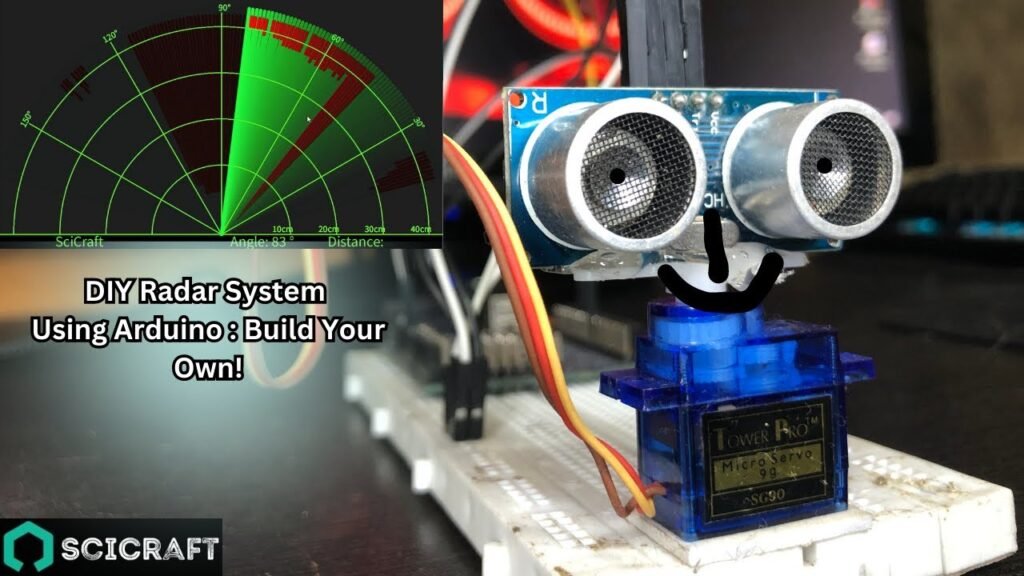
Radar systems are used in defense, automation, robotics, and navigation. In this DIY project, we’ll build a Radar System using Arduino, an HC-SR04 ultrasonic sensor, and a servo motor to scan the environment. The system will sweep a certain angle, detect objects, and visualize them as radar blips on a screen using Processing (optional).
This project is ideal for students, hobbyists, and developers who want to dive into object detection and servo control using Arduino.
⚙️ Components Required
Arduino Uno or Nano
HC-SR04 Ultrasonic Sensor
SG90 Servo Motor
Jumper Wires
Breadboard
USB Cable
Optional: Processing Software (for radar visualization on PC)
🔌 Circuit Diagram and Pinout
Pin Connections:
| Component | Arduino Pin |
|---|---|
| HC-SR04 Trigger Pin | D9 |
| HC-SR04 Echo Pin | D10 |
| Servo Motor Signal | D6 |
| VCC (Both) | 5V |
| GND (Both) | GND |
Pinout Tip:
Connect the ultrasonic sensor and servo carefully to avoid voltage drops. Use external power for the servo if it jitters.
💡 How It Works
The servo motor rotates the ultrasonic sensor from 0° to 180° and back.
At each angle, the sensor sends out ultrasonic waves and waits for the echo.
The time taken for the echo to return is used to calculate the distance.
The distance and angle are either:
Displayed in the Serial Monitor, or
Visualized on a radar GUI via Processing software.
🧾 Arduino Code
#include <Servo.h>
const int trigPin = 9;
const int echoPin = 10;
Servo myServo;void setup() {
Serial.begin(9600);
myServo.attach(6);
pinMode(trigPin, OUTPUT);
pinMode(echoPin, INPUT);
}void loop() {
for(int angle = 0; angle <= 180; angle++){
myServo.write(angle);
delay(30);
long duration, distance;
digitalWrite(trigPin, LOW);
delayMicroseconds(2);
digitalWrite(trigPin, HIGH);
delayMicroseconds(10);
digitalWrite(trigPin, LOW);
duration = pulseIn(echoPin, HIGH);
distance = duration * 0.034 / 2;Serial.print(angle);
Serial.print(“,”);
Serial.println(distance);
}for(int angle = 180; angle >= 0; angle–){
myServo.write(angle);
delay(30);
long duration, distance;
digitalWrite(trigPin, LOW);
delayMicroseconds(2);
digitalWrite(trigPin, HIGH);
delayMicroseconds(10);
digitalWrite(trigPin, LOW);
duration = pulseIn(echoPin, HIGH);
distance = duration * 0.034 / 2;Serial.print(angle);
Serial.print(“,”);
Serial.println(distance);
}
}🎯 Optional: Radar Visualization Using Processing
Download and install Processing.
Use the Serial data from Arduino to plot a radar-style UI.
Code is available online or we can help generate a custom one for your readers.
🪛 Assembly Instructions
Mount the ultrasonic sensor on top of the servo motor using glue or double-sided tape.
Connect wires as per the pinout diagram.
Upload the Arduino code via the Arduino IDE.
Open the Serial Monitor to see live distance data.
Use Processing for a visual radar interface.
🌿 Applications
Object detection in robotics
Entry-level radar simulation
Surveillance or obstacle alert systems
Educational electronics projects
🔄 Advanced Upgrades
Display radar data on an OLED display
Add buzzer alerts for specific distance thresholds
Build a 360° rotating base for full scan
Connect to a mobile app using Bluetooth or Wi-Fi