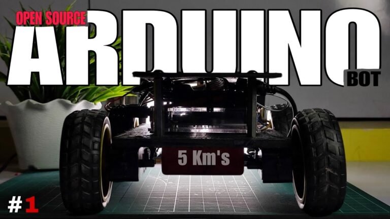

 DIY RC Car Controlled with Flysky Transmitter (Arduino + L298N Guide)
In this project tutorial, you'll learn how to build a custom Arduino-based RC car that is remotely controlled using the Flysky FS-i6s radio transmitter. We’ll walk you through everything — from transmitter channel setup to motor driver integration — so that you can bring your radio-controlled vehicle to life using widely available electronic components.
Whether you're a beginner or an RC enthusiast, this guide offers a practical learning experience in robotics, embedded systems, and RC communication.
 Transmitter Configuration:
Set AUX Channel 5 → SWB (Switch B)
Set Channel 6 → SWA (Switch A)
This step ensures that your transmitter toggles can control speed and steering on separate channels for smooth operation.
 Components Used:
L298N Motor Driver
Arduino Uno
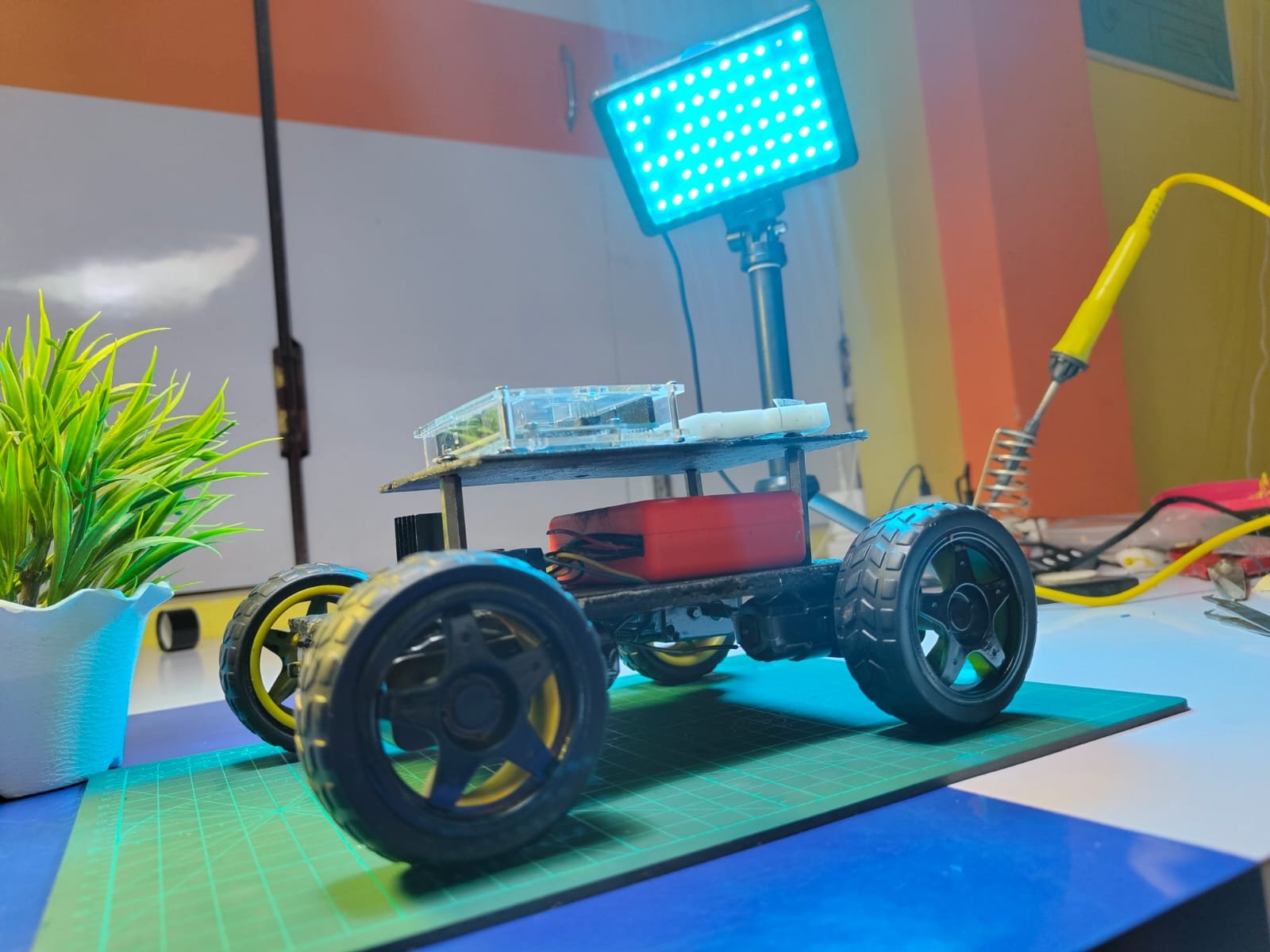
12V Battery Pack
2× BO Motors
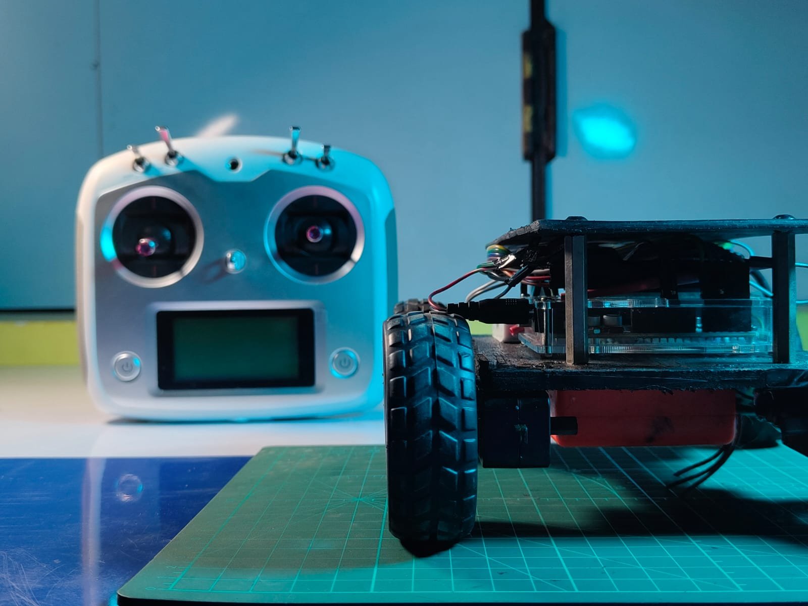
Flysky FS-i6s Transmitter & Receiver
Jumper Cables
Wheels & Chassis
You can access the Arduino code and connection diagram by visiting the following page: Code & Schematics – View on Tinkerzy
 Suggested Image Spaces:
Close-up of Flysky transmitter setup
Wiring diagram with Arduino + L298N + RX
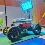
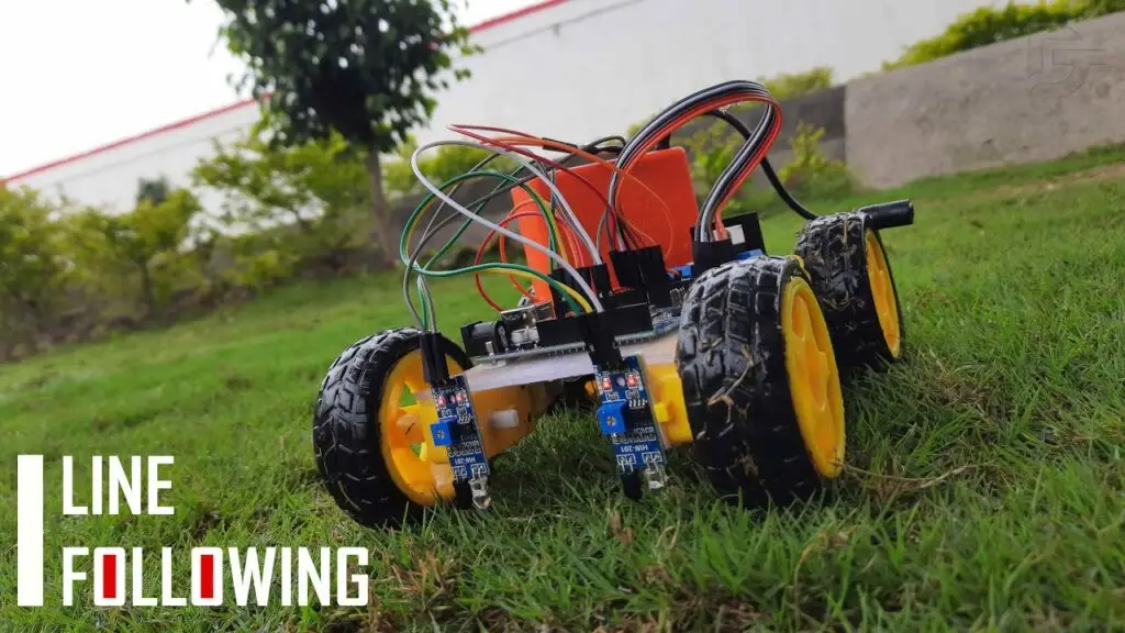
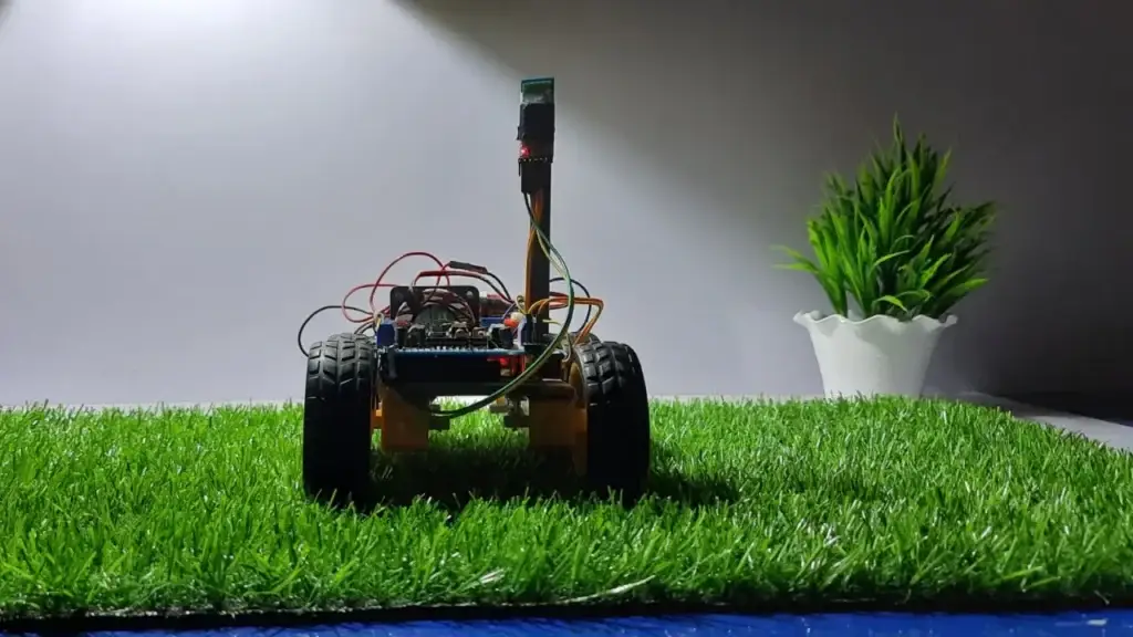
Side view of assembled car
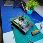
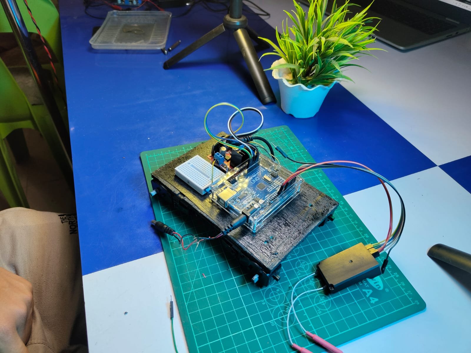
Top-down photo of mounted electronics
—
 Step-by-Step Instructions:
Step 1: Assemble your chassis and securely mount the BO motors and wheels.
→ N motor driver outputs (OUT1/OUT2 and OUT3/OUT4).
Step 3: Wire the L298N inputs (IN1, IN2, IN3, IN4) to Arduino digital pins (you can choose 6, 7, 8, 9 for example).
Step 4: Power the motor driver with a 12V battery. Connect the GND to Arduino’s GND.
Step 5: Connect the Flysky receiver's signal pins (usually CH1 and CH2) to Arduino analog pins (A0 and A1).
→
Step 6: In the transmitter, assign Channel 5 to Switch B and Channel 6 to Switch A under the AUX Channel settings menu.
Step 7: Upload the control code using the Arduino IDE. The code reads PWM values from the RX and drives the motors accordingly.
→
—
 What You’ll Learn:
Basics of motor control using L298N
How PWM signals from RC receivers are interpreted by Arduino
Transmitter channel configuration and mapping
Integration of mechanical and electronic systems for RC projects
 Follow for More Projects: Want behind-the-scenes content and direct Q&A access?
Follow me on Instagram → @drab_tech
 Business Inquiries or Collaborations: Email me at drabtech@gmail.com
—
 Explore More Projects: Want to build a WiFi-controlled bot, GPS tracker, or Arduino drone?
Check out my full archive of DIY projects here → Click to explore on Tinkerzy
—
This content is purely educational and designed to help you better understand how RC systems work with microcontrollers. As always, build responsibly and safely.


