


| Image | Product | Quantity | Buy |
|---|---|---|---|
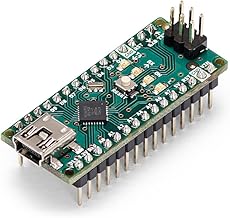 | Arduino | 1 | |
 | Adafruit Trinket - 5V Mini Microcontroller - ATtiny85, 8K Flash, 512 SRAM, 512 EEPROM, USB, I2C, SPI, Infrared, Single Board Computer, Microcontroller | 1 | |
 | 10PCS 8 RGB LED Stick 8 X WS2812B 5050 RGB LED with Integrated Drivers forArduino Raspberry Pi DC4-7V | 1 | |
| — | PCMWay Custom Pcb | 1 | — |
| — | Autodesk Fusion | 1 | — |
| — | Arduino IDE | 1 | — |
| — | 3D Printer | 1 | — |