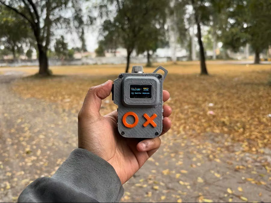


Because of its small size and built-in power supply, the user can gather air quality readings anywhere they go.
The concentration of specific gases in the air is indicated by this air quality meter, however it is not the same as a complete Air Quality Index (AQI) evaluation. Initially particulate matter (PM2.5 and PM10), oxygen, nitrogen dioxide, sulfur dioxide, and carbon monoxide are commonly monitored in air quality index monitoring. The only gases that our setup can detect are CO2, smoke, benzene, alcohol, nitrogen oxide, and ammonia.
The thorough and standardized AQI used for public health advisories is still the best source of information, but our air quality meter is a terrific tool for gaining a general understanding of the air quality in terms of specific gases.
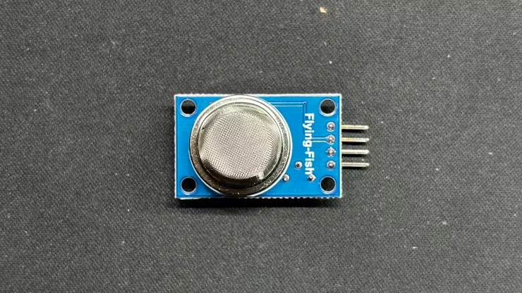
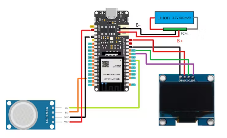
The inside components of this project include the MQ135 Air Quality Sensor, the SSD1306 Display, a tiny 14500 3.7V 600mAh Li-ion cell, and the Firebeetle 2 ESP32 Microcontroller, which serves as the project's brain. All of these components come together in a customized body that we 3D printed.
Let us begin the build since this article covers the entire meter's construction process.
Materials requiredThese are the materials used in this build-
- MQ135 Air Quality Sensor (Got from PCBWAY GIFTSHOP)
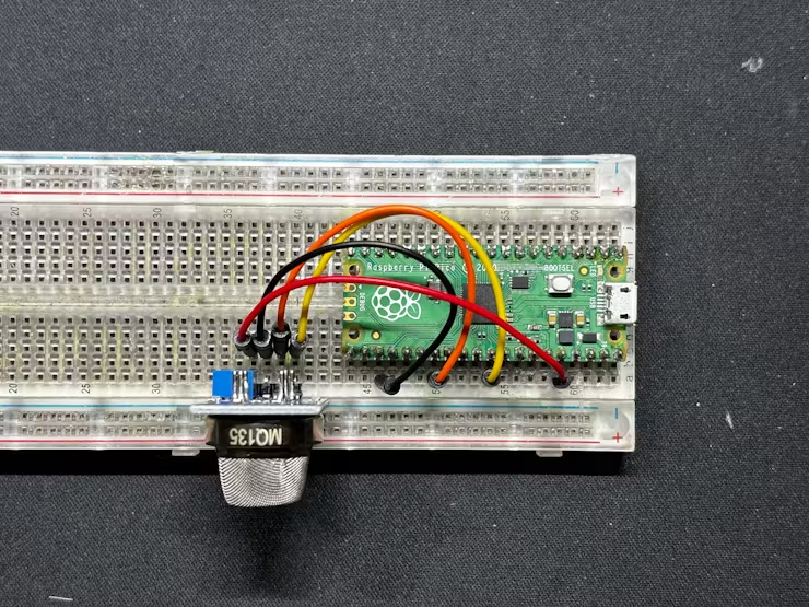
- Raspberry Pi PICO 2
- BREADBOARD
- 3D-PRINTED BODY
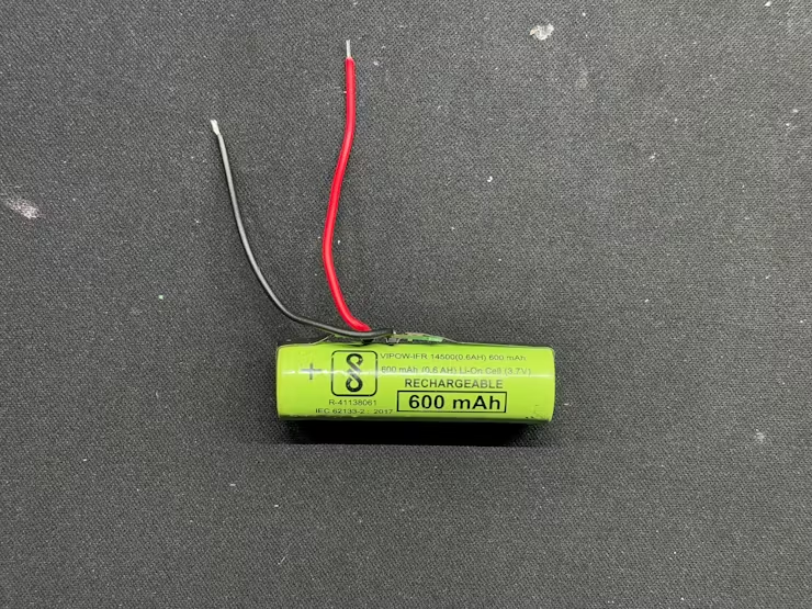
- 14500 3.7V 600mAh Li-ion cell with PCM
- ROCKER SWITCH SPST
- FireBeetle 2 ESP32-E DEV BOARD
- SSD1306 OLED SCREEN
- connecting wires
- M2 Screws
Level 2- Design
We made a little enclosure in the Level 2 design that was just 80 x 55 x 30 mm in size. It was separated into two bodies: the Base and the Top Lid part. The OLED screen is mounted in place inside top lid part.
The Firebeetle 2 Board, MQ135 Sensor, Power Switch, and Battery are all housed inside the Base Body.
We added handles to the left and right sides of the base body to make this enclosure comfortable and easy to hold.
To make it easier to wear or carry around, we have included a hook-like component that can be used to attach an ID card strap or a keychain to this device.
We created two additional components that resemble the letters O and X and put them to the top lid part of the enclosure to increase its visual impact. To enhance the device's aesthetic impact, both of these parts will be printed in orange PLA, while the entire enclosure will be printed in grey PLA.
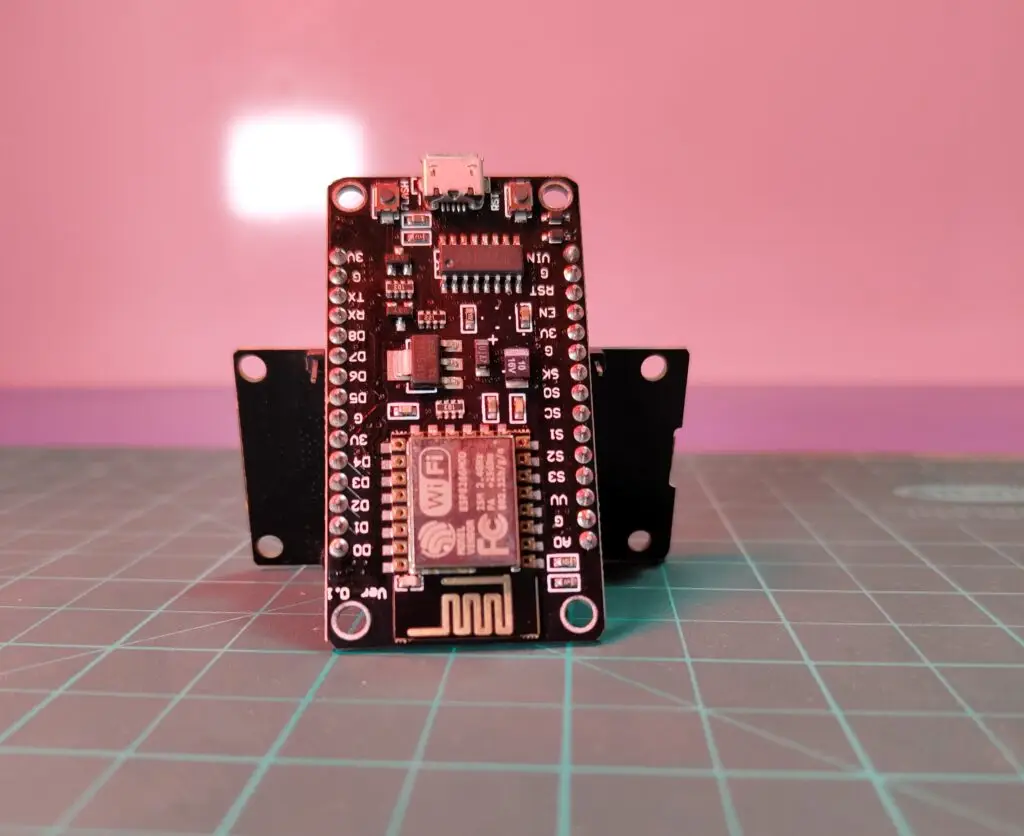
Why Choose FireBeetle over Raspberry Pi PicoFor level 2 of this project, we swapped the main microcontroller used, which was the Raspberry Pi Pico 2, to the Firebeetle 2 ESP32-E Microcontroller board.
A minor space issue within the enclosure was the reason for this switch, however despite the fact that the two boards appear to be almost identical in size, the Pico is really smaller than the Firebeetle. We had to modify the enclosure's design and make it slightly larger because using Pico required the addition of a second board for charging the lithium cell.
We utilized the Firebeetle to address this issue since it has an onboard lithium-ion cell charging circuit that is driven by the TP4056, a full linear charger integrated circuit made specifically for single-cell lithium-ion batteries.
The TP4065 was incorporated into the Firebeetle development board, which resolved our space issue. It is perfect for usage in portable devices that need a dependable and effective lithium-ion battery charging solution.
MAIN SKETCHLet's have a look at the final Sketch which will be used in Firebeetle Setup.
#include <Wire.h>
#include <Adafruit_GFX.h>
#include <Adafruit_SSD1306.h>
#define SCREEN_WIDTH 128
#define SCREEN_HEIGHT 64
#define OLED_RESET    -1
Adafruit_SSD1306 display(SCREEN_WIDTH, SCREEN_HEIGHT, &Wire, OLED_RESET);
const int analogPin = 35;  // A3
const int digitalPin = 2;  // D2
void setup() {
Serial.begin(9600);
pinMode(digitalPin, INPUT);
// SSD1306 OLED display initialization
if (!display.begin(SSD1306_SWITCHCAPVCC, 0x3C)) {
Serial.println(F("SSD1306 allocation failed"));
for(;;);
}
display.display();
delay(2000); // Pause for 2 seconds
display.clearDisplay();
}
void loop() {
int analogValueRaw = analogRead(analogPin);
int analogValue = map(analogValueRaw, 0, 4095, 0, 1023);  // Scale the value to match the Pico's range
int digitalValue = digitalRead(digitalPin);
String airQuality = getAirQuality(analogValue);
Serial.print("Analog Value (Raw): ");
Serial.print(analogValueRaw);
Serial.print(", Scaled Value: ");
Serial.print(analogValue);
Serial.print(", Digital Value: ");
Serial.println(digitalValue);
// Display scaled analog value and air quality condition on OLED
display.clearDisplay();
display.setTextSize(2);      // Normal 1:1 pixel scale
display.setTextColor(SSD1306_WHITE); // Draw white text
display.setCursor(0, 10);    // Start at top-left corner
display.print("Value: ");
display.println(analogValue);
display.setTextSize(1);
display.setCursor(0, 40);
display.print("Air Quality: ");
display.println(airQuality);
display.display();
delay(1000);
}
String getAirQuality(int analogValue) {
if (analogValue <= 200) {
return "Excellent";
} else if (analogValue <= 400) {
return "Good";
} else if (analogValue <= 600) {
return "Moderate";
} else if (analogValue <= 800) {
return "Poor";
} else {
return "Very Poor";
}
}
The three main libraries in the sketch were added specifically to use I2C communication to drive the SSD1306 OLED.
Two outputs are provided by the MQ135 sensor: an analog output that is attached to the Firebeetle's A3 pin and a digital output that is connected to the Firebeetle's D2.
We must reduce the raw analog value, which is around 0-4095, to a range of 0-1023 in order to obtain the analog value, which is what we need to obtain the air quality measurements.
Using the Serial.println function, the values are displayed on the screen, but with a twist. The twist here is that we have added getAirQuality Function which takes the scaled analog value and returns a string representing the air quality condition:
- <= 200: "Excellent"
- <= 400: "Good"
- <= 600: "Moderate"
- <= 800: "Poor"
- > 800: "Very Poor"
- We positioned the OLED screen inside the top lid to begin the body assembly process, and then we used hot glue to secure the display in place.
- Within the Base body, the MQ135 Sensor is then slide into place.
- The battery and power switch are next fastened in their proper positions, and the Firebeetle Board is placed in the center of the base body and fastened there using hot glue.
- After ensuring that everything was in its proper place, we placed the Top Lid over the base body and fastened them together with four M2 screws.
- We finish by applying super glue to the back of the letter O and X parts before positioning them onto the device.
Assembly process is now completed.
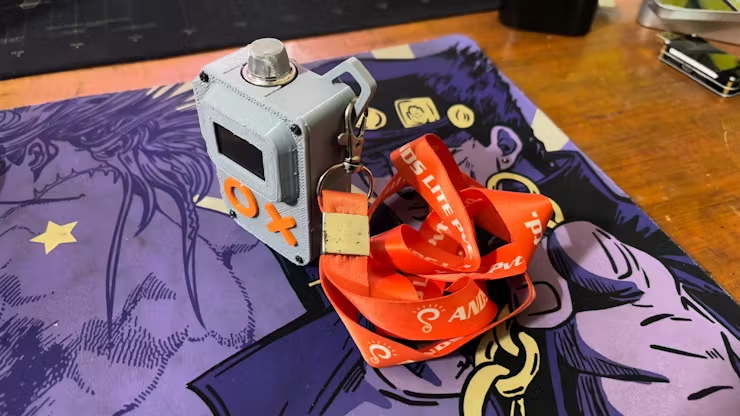
We took readings in two different locations in my city to test our setup: on my rooftop and close to a green area. The low carbon concentration in the green area contrasts with the high carbon concentration in the city, which is why we got different readings.
The city's readings ranged from 550 to 620, depending on whether the area was close to a major road, an industrial region, or a green space with lots of trees and few cars.
If we take the tests in places where gases are less common, such mountains or hills, the values may drop much further.
Overall, this setup was finished, but I would like to make revisions to this project in the future to further reduce its size and make it extremely portable.