Things Used in This Project
Hardware Components:
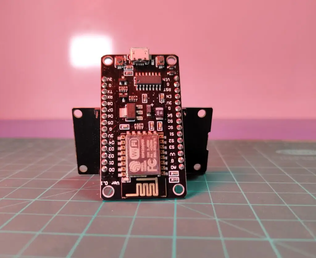
XIAO ESP32 C3 – Seeed Studio XIAO ESP32 C3
WiFi Antenna
Custom PCB
AO3400 N-Channel MOSFET
5V Relay
Isolated Power Module
16A AC Plug
16A AC Socket
3D Printed Parts
Software Apps and Online Services:
Autodesk Fusion – For 3D modeling of plug components
Arduino IDE – For programming the XIAO ESP32 C3 microcontroller
Hand Tools and Fabrication Machines:
Seeed Studio Fusion PCB/PCBA – For PCB manufacturing and assembly
Story
Greeting everyone! Welcome back to another project. In this one, we’re adding some warmth with a WiFi Smart Plug designed to remotely control our room heater.
The concept behind this idea is simple: It can be inconvenient to manually turn the heater on or off. So, why not add IoT functionality and convert the room heater into a smart heater that can be controlled from anywhere?
However, designing an IoT heater that only works during winter seemed limiting. So, we turned our project into a Smart Plug that can be used year-round – controlling a heater in winter and an air conditioner in summer.
The Smart Plug uses a XIAO ESP32 C3 microcontroller combined with a custom relay driver board. The relay board houses an isolated power source that powers the XIAO and controls the AC load. The user can simply use a web app to turn the heater (or other devices) on or off, and it works seamlessly across devices like smartphones, tablets, and PCs.
This article will walk you through the build process, materials, and design steps for creating this WiFi Smart Plug.
Materials Required
XIAO ESP32 C3 – For WiFi control
WiFi Antenna
Custom PCB – For the relay and driver circuit
AO3400 N-channel MOSFET – Used for switching
5V Relay – To control the AC load
Isolated Power Module – To convert 240V AC to 5V DC for the microcontroller
16A AC Plug – For connecting devices like heaters or air conditioners
16A AC Socket
3D Printed Parts – For the plug and socket housing
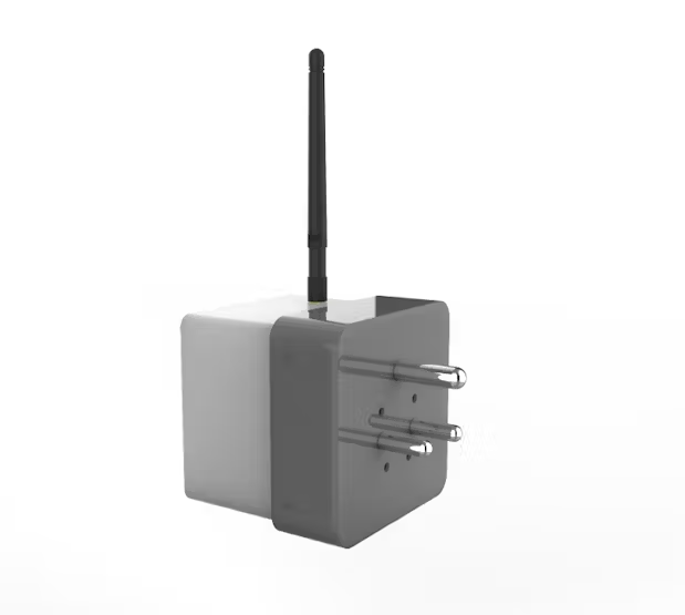
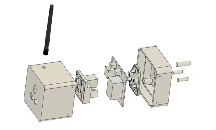
Design of the Plug
We began the design by repurposing our XIAO Relay Driver Board. This board consists of an N-channel MOSFET, a relay, and an isolated power module to safely manage the power requirements of the plug.
The design focuses on reducing the plug size while retaining essential components. The socket and plug housings are made of thermal-grade PC (Polycarbonate) to withstand the heat produced by high power loads, as regular PLA would not be adequate for this purpose.
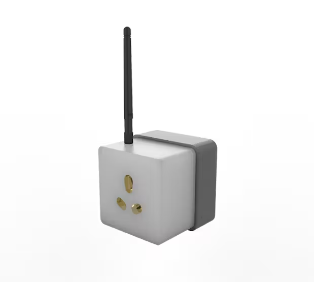
The model was split into two sections: the socket section and the plug section. We used transparent PLA for the socket section to highlight the internals, and gray PLA for the plug section for a contrasting two-tone look.
We also made sure that the housing fits BS 546 plug sockets, which are standard in India and can handle up to 250V AC.
PCB Design: XIAO Relay Board
For this project, we used a custom PCB based on our previously designed XIAO Relay Board. The key components include:
XIAO ESP32 C3 microcontroller
AO3400 N-channel MOSFET
5V Relay
Isolated Power Module for 240V to 5V conversion
After finalizing the design and generating the Gerber files, we sent the design to Seeed Studio Fusion for PCB fabrication and assembly. The boards were produced with a blue solder mask and white silkscreen, offering great quality at an affordable price.
PCB Assembly Process
Solder Paste Application: We start by applying 63/37 Sn/Pb solder paste on each SMD component pad using a dispensing needle.
Component Placement: Each SMD component is placed on the PCB with the help of an ESD Tweezer.
Reflow Process: The board is heated to 190°C using a reflow hotplate, which melts the solder paste and secures the components.
Through-Hole Components: After placing the SMDs, through-hole components like CON7 header pins, relay, and power module are inserted and soldered.
XIAO ESP32 C3: Finally, the XIAO ESP32 C3 is installed on the board and connected to the relay and power module.
Main Sketch
The Arduino code running on the XIAO ESP32 C3 allows control over the relay using a simple web interface.
Here’s a simplified version of the main code for the smart plug:
#include <WiFi.h>
#include <ESPAsyncWebServer.h>

const char* ssid = "YOUR_SSID";
const char* password = "YOUR_PASSWORD";
#define RELAY_PIN D1
#define LED_PIN D0

AsyncWebServer server(80);
bool relayState = false;

void setup() {
Serial.begin(115200);
WiFi.begin(ssid, password);
while (WiFi.status() != WL_CONNECTED) {
delay(1000);
Serial.println("Connecting to WiFi...");
}
Serial.println("Connected to WiFi");
Serial.print("IP Address: ");
Serial.println(WiFi.localIP());

pinMode(RELAY_PIN, OUTPUT);
pinMode(LED_PIN, OUTPUT);
digitalWrite(RELAY_PIN, LOW);
digitalWrite(LED_PIN, LOW);

server.on("/", HTTP_GET, [](AsyncWebServerRequest *request){
request->send(200, "text/html", "<html><body><h2>Smart WiFi Plug</h2><button onclick='fetch("/toggle");'>Toggle Relay</button></body></html>");
});

server.on("/toggle", HTTP_GET, [](AsyncWebServerRequest *request){
relayState = !relayState;
digitalWrite(RELAY_PIN, relayState);
digitalWrite(LED_PIN, relayState ? HIGH : LOW);
request->send(200, "text/plain", "Toggled!");
});

server.begin();
}

void loop() {}
This code runs a simple web server on the XIAO ESP32, where users can toggle the relay (controlling the heater or air conditioner) with a button press on a webpage.
Assembly Process
Plug Section Assembly: The AC plug is placed inside the 3D printed housing and secured using the AC pins.
Wiring: Live and Neutral wires are connected from the AC plug to the relay circuit. We used 2.5 sq/mm wire rated for 3500-5000W loads to ensure safety.
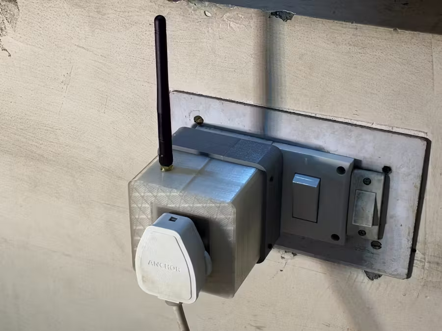
Socket Section Assembly: The AC socket is installed into the housing and fastened with M2 screws. The WiFi antenna is also mounted in this section.
Finally, the plug and socket sections are connected, and the WiFi antenna is linked to the XIAO ESP32. This completes the physical assembly of the Smart Room Heater Plug.
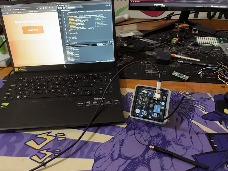
Testing and Final Results
After assembling the plug, we tested it by plugging it into a 16A socket and connecting a room heater to the onboard socket. The XIAO ESP32 successfully connected to WiFi, and we could control the heater remotely through the webpage interface.
This project turned out to be a huge success, providing a simple way to control room heating from the comfort of your couch.
The Smart Plug is now fully functional, and in the future, we plan to add more advanced features like timers and smart scheduling.
Final Thoughts
The Smart Room Heater Plug project has accomplished its goal of adding IoT functionality to a conventional room heater. It provides a seamless experience where you can turn your heater on or off from anywhere, using any connected device.
If you have any questions or need assistance, feel free to leave a comment.
A big thanks to Seeed Studio Fusion for their support with PCB fabrication and assembly!
Stay tuned for more projects, and I’ll be back soon with a new build.